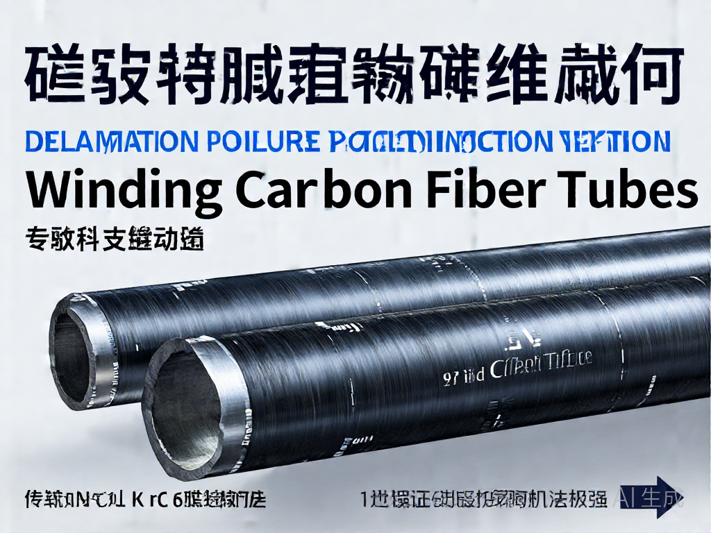
# Delamination Failure Position Inspection Method for Winding Carbon Fiber Tubes
## Introduction
Winding carbon fiber tubes are widely used in aerospace, automotive, and sports equipment due to their high strength-to-weight ratio. However, delamination—a separation between layers—is a critical failure mode that can compromise structural integrity. Detecting the exact position of delamination is essential for quality control and safety. This article presents a systematic inspection method to locate delamination in winding carbon fiber tubes, covering visual inspection, ultrasonic testing, and advanced techniques.
## Understanding Delamination in Winding Carbon Fiber Tubes
Delamination occurs when the bond between adjacent layers of carbon fiber reinforced polymer (CFRP) fails. In winding tubes, this can result from inadequate impregnation, voids, or thermal stresses during curing. Early detection of delamination position allows for targeted repairs or rejection, preventing catastrophic failures.
## Step-by-Step Inspection Method
### 1. Visual Inspection
Begin with a thorough visual examination of the tube’s surface. Look for signs of delamination such as bulges, cracks, or discoloration. Use a magnifying glass and bright lighting. Mark any suspicious areas for further testing. While visual inspection cannot detect internal delamination, it provides initial clues.
### 2. Tap Testing
Gently tap the tube surface with a coin or small hammer. A clear, ringing sound indicates good bonding, while a dull thud suggests delamination. Systematically tap along the tube’s length and circumference, marking areas with abnormal sounds. This method is quick and effective for near-surface defects.
### 3. Ultrasonic Testing
Ultrasonic testing (UT) is the most reliable method for locating internal delamination. Use a portable ultrasonic flaw detector with a high-frequency transducer (e.g., 5 MHz). Apply couplant to the tube surface and scan in a grid pattern. Delamination appears as a loss of back-wall echo or an intermediate echo. Record the coordinates of anomalies to map the delamination position.
#### 3.1 Through-Transmission Technique
For thicker tubes, use through-transmission UT. Place transmitter and receiver on opposite sides of the tube. A reduction in transmitted signal indicates delamination. This technique is effective for detecting deep-seated defects.
### 4. Acoustic Emission Testing
Acoustic emission (AE) monitoring can detect delamination growth under load. Attach AE sensors to the tube and apply incremental loading. Delamination generates high-frequency acoustic signals. By triangulating signals from multiple sensors, you can locate the delamination position in real-time.
### 5. X-ray Computed Tomography (CT)
For critical applications, X-ray CT provides a 3D view of internal defects. Scan the tube and analyze cross-sectional images to identify delamination planes. CT is expensive but offers precise positional information.
## Best Practices for Accurate Delamination Positioning
– Calibrate equipment regularly.
– Use a grid system to record scan positions.
– Combine methods for cross-validation.
– Train inspectors on interpreting signals.
– Document all findings with photographs and coordinates.
## Conclusion
Locating delamination in winding carbon fiber tubes requires a multi-technique approach. Start with visual and tap testing, then use ultrasonic testing for internal defects. Advanced methods like acoustic emission and CT scanning provide precise positioning for critical components. Implementing this inspection method ensures reliable quality control and extends the service life of carbon fiber tubes.