
## Introduction
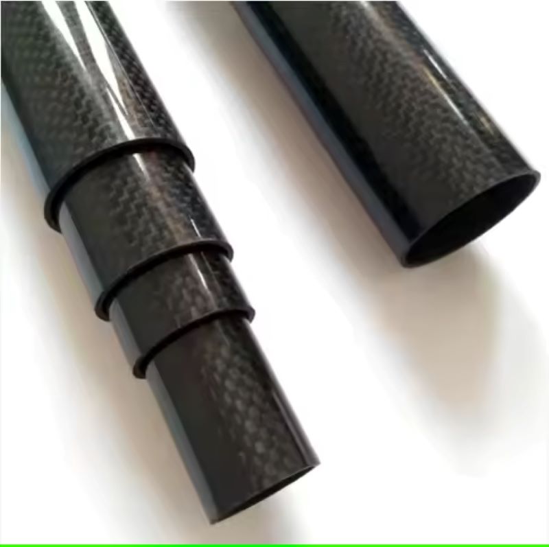
In modern engineering, carbon fiber reinforced polymer (CFRP) tubes are favored for their high specific strength and stiffness. However, many load-bearing structures experience uneven stress distributions—concentrated at joints, supports, or bending zones—while other regions remain lightly loaded. A uniform wall thickness tube is inefficient in such cases, adding unnecessary weight and cost. Variable wall thickness (VWT) carbon tube design addresses this by tailoring the material distribution to match the actual load profile, achieving optimal structural efficiency. This article explores the design logic, manufacturing considerations, and practical applications of VWT carbon tubes for uneven load-bearing equipment.
## Understanding Uneven Load Distribution
Uneven loads are common in equipment like robotic arms, wind turbine blades, bicycle frames, and aerospace actuators. These structures often experience:
– **High bending moments** near fixed ends or supports.
– **Concentrated contact stresses** at mounting points.
– **Torsional loads** that vary along the length.
– **Dynamic or fatigue loads** that create localized stress peaks.
A uniform tube must be sized to the maximum stress point, leading to overdesign in low-stress regions. VWT design allows the wall to be thicker where stress is high and thinner where it is low, reducing weight without compromising strength or stiffness.
## Core Design Logic for Variable Wall Thickness
### 1. Load Path Analysis
The first step is to map the load path along the tube length. Using finite element analysis (FEA), engineers identify the distribution of axial, bending, and shear stresses. For example, a cantilever beam has maximum bending stress at the fixed end, decreasing linearly to zero at the free end. This suggests a tapered wall thickness profile.
### 2. Stress-Based Thickness Optimization
For each cross-section, the required wall thickness is calculated based on the allowable stress of the carbon composite. The thickness is set so that the maximum stress in that section equals the material’s design limit. This results in a thickness profile that follows the stress envelope.
### 3. Stiffness and Buckling Constraints
While strength is critical, stiffness (deflection) and local buckling must also be considered. Thin-walled sections may buckle under compressive loads. Therefore, the minimum wall thickness is often governed by buckling stability, not just stress. Designers must ensure that even the thinnest section meets a critical buckling load.
### 4. Transition Smoothness
Abrupt changes in wall thickness create stress concentrations and manufacturing defects. The thickness should transition gradually, with a taper ratio (change in thickness per unit length) that limits interlaminar shear stresses. Typically, a taper angle of less than 10 degrees is recommended.
### 5. Ply Drop-Off Scheduling
In laminated composites, variable thickness is achieved by dropping off plies. The sequence of ply terminations must be carefully scheduled to avoid delamination. Plies are dropped symmetrically and in a staggered pattern to maintain balance and minimize stress concentrations at the drop-off points.
## Manufacturing Methods for Variable Wall Thickness
### Filament Winding with Variable Feed
In filament winding, the wall thickness can be varied by controlling the winding angle and the number of passes over specific sections. By programming the machine to add more layers at high-stress zones, a near-net-shape VWT tube can be produced. This method is efficient for cylindrical or slightly tapered tubes.
### Roll Wrapping with Ply Drops
For rectangular or non-circular tubes, roll wrapping is common. Pre-preg sheets are wrapped around a mandrel, and plies are added or dropped at predetermined locations. This allows precise control of thickness but requires careful handling of ply drop-offs.
### Pultrusion with Variable Die
Pultrusion is typically used for constant cross-sections, but with a specially designed die, the wall thickness can be varied along the length. However, this is complex and limited to simple profiles. It is rarely used for VWT due to high tooling costs.
### Additive Manufacturing (3D Printing)
Emerging continuous fiber 3D printing can create truly variable thickness with complex internal structures. While still limited in scale, this method offers design freedom for prototypes and small series.
## Structural Performance Benefits
### Weight Reduction
By removing material from low-stress regions, VWT tubes can achieve weight savings of 20–40% compared to uniform tubes, depending on the load profile. This is critical in aerospace and automotive applications where every gram counts.
### Improved Strength-to-Weight Ratio
The material is used where it is needed most, resulting in a higher overall structural efficiency. This allows equipment to handle higher loads without increasing weight.
### Enhanced Fatigue Life
By reducing stress concentrations and avoiding overloading in certain sections, VWT tubes can have better fatigue resistance. The gradual thickness transitions also reduce stress risers.
### Tailored Stiffness
VWT allows engineers to tune the bending and torsional stiffness along the tube. For example, a robotic arm can be stiff near the base and flexible at the tip, improving dynamic performance.
## Design Challenges and Solutions
### Delamination Risk at Ply Drops
Ply drop-offs are potential initiation points for delamination. Solutions include:
– Using interleaving plies (e.g., adding a thin glass layer) to reduce interlaminar stresses.
– Ensuring a minimum drop-off spacing (typically 10–20 times the ply thickness).
– Applying local reinforcement like stitching or z-pinning.
### Manufacturing Complexity
VWT tubes require more complex molds, mandrels, and winding programs. This increases initial tooling cost and production time. However, for high-volume applications, the weight savings often justify the investment.
### Quality Control
Non-destructive testing (NDT) is essential to verify thickness variations and detect voids or delaminations. Ultrasonic testing and computed tomography (CT) are commonly used.
### Cost Considerations
The added manufacturing complexity increases cost per part. Therefore, VWT is most beneficial when:
– Weight reduction is a high priority (aerospace, racing).
– The load profile is well understood and consistent.
– Production volume is high enough to amortize tooling.
## Applications in Uneven Load-Bearing Equipment
### Robotic Arms and Actuators
Robotic arms experience high bending moments at the base and lower loads at the end effector. VWT tubes reduce arm weight, improving speed and energy efficiency while maintaining precision.
### Wind Turbine Blades
Although blades are not tubes, similar logic applies to spar caps. VWT carbon tubes are used in the spar structure to handle varying bending loads along the blade length.
### Bicycle and Motorcycle Frames
Frame tubes are subjected to concentrated loads at welds and joints. VWT tubes allow lighter frames without sacrificing stiffness or durability.
### Aerospace Actuators and Struts
Landing gear struts and control rods experience high axial and bending loads at attachment points. VWT tubes reduce weight, contributing to fuel savings.
### Sports Equipment
Golf shafts, hockey sticks, and ski poles benefit from VWT to optimize flex and strength profiles.
## Conclusion
Variable wall thickness carbon tube design is a powerful approach for uneven load-bearing equipment. By aligning material distribution with the actual stress field, engineers can achieve significant weight savings, improved structural performance, and tailored stiffness. The design logic involves careful load analysis, stress-based thickness optimization, and consideration of buckling and manufacturing constraints. While challenges such as delamination and cost exist, they can be mitigated with proper ply scheduling and quality control. As manufacturing technologies advance, VWT carbon tubes will become increasingly accessible, enabling lighter and more efficient equipment across industries.