
## Introduction
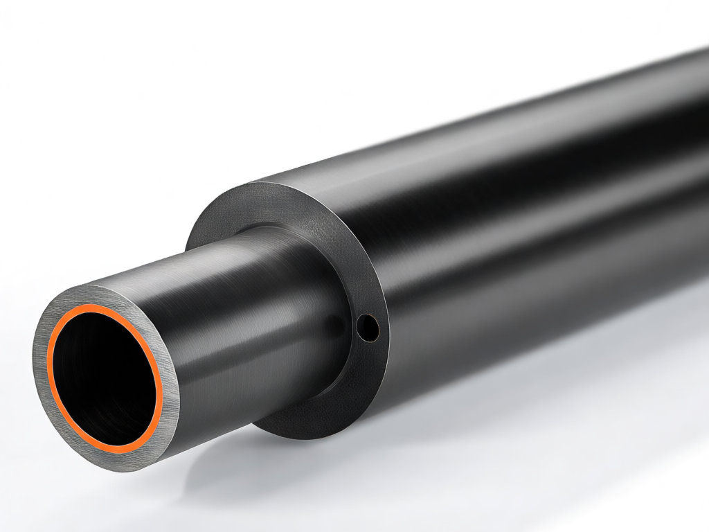
Carbon fiber reinforced polymer (CFRP) tubes are increasingly used in aerospace, automotive, and sports equipment due to their high strength-to-weight ratio. However, machining lateral through-holes in these tubes introduces stress concentrations that can lead to premature failure. This article provides essential design tips for stress release when processing lateral through-holes in carbon tubes, ensuring structural integrity and longevity.
## Understanding Stress Concentration in Carbon Tubes
When a hole is drilled into a carbon tube, the continuous fiber path is interrupted, causing stress concentrations around the hole. Unlike metals, carbon fiber composites are anisotropic and brittle, making them more sensitive to stress raisers. The lateral through-hole, in particular, creates a complex stress state due to the curvature of the tube and the direction of loading.
### Factors Affecting Stress Concentration
– **Hole diameter and tube thickness**: Larger holes and thinner walls increase stress concentration.
– **Hole location**: Holes near the tube ends or in high-bending regions are more critical.
– **Fiber orientation**: The layup sequence determines how stresses are distributed.
– **Loading conditions**: Tension, compression, torsion, or combined loads affect the severity.
## Design Tips for Stress Release
### 1. Optimize Hole Geometry
– **Use elliptical or oval holes**: Instead of circular holes, elliptical shapes can reduce stress concentration by distributing stresses over a larger area. Orient the major axis along the tube axis to minimize disruption of load-carrying fibers.
– **Add chamfers or fillets**: Rounding the edges of the hole reduces stress concentration. A chamfer or fillet with a radius of at least 0.5 mm can significantly lower peak stresses.
– **Avoid sharp corners**: Ensure all transitions are smooth to prevent crack initiation.
### 2. Reinforce the Hole Region
– **Local thickening**: Increase the wall thickness around the hole by adding extra plies or using a doubler. This compensates for the material removed and reduces stress levels.
– **Use inserts or bushings**: Metallic or composite inserts can distribute loads and protect the carbon tube from bearing stresses. Ensure the insert is bonded or mechanically fastened without creating new stress points.
– **Fiber steering**: In advanced manufacturing, steer fibers around the hole to maintain continuity. This requires specialized tooling but can dramatically improve strength.
### 3. Consider the Drilling Process
– **Use diamond-coated tools**: Carbide or diamond-coated drill bits reduce delamination and fiber pull-out. High-speed drilling with low feed rates minimizes damage.
– **Support the tube**: Back-up plates or mandrels prevent deformation and reduce exit delamination.
– **Coolant**: Use adequate cooling to prevent overheating, which can degrade the resin matrix.
### 4. Analyze and Test
– **Finite element analysis (FEA)**: Model the tube with the hole under expected loads to identify stress hotspots. Iterate the design to achieve a safety factor of at least 2.
– **Prototype testing**: Conduct static and fatigue tests on samples with the proposed hole design. Use strain gauges to validate FEA results.
– **Non-destructive testing**: After machining, inspect for delamination or cracks using ultrasonic or X-ray methods.
### 5. Additional Design Considerations
– **Hole spacing**: If multiple holes are needed, maintain adequate spacing (at least 3 times the hole diameter) to avoid interaction effects.
– **Edge distance**: Keep holes at least 2.5 times the diameter away from tube ends to prevent edge failure.
– **Load direction**: Orient holes perpendicular to the principal load direction when possible to reduce stress intensity.
## Conclusion
Designing lateral through-holes in carbon tubes requires careful attention to stress release. By optimizing hole geometry, reinforcing the region, using proper machining techniques, and validating with analysis and testing, engineers can ensure that the holes do not compromise the tube’s performance. These tips will help you achieve reliable, lightweight structures that meet the demands of high-performance applications.