
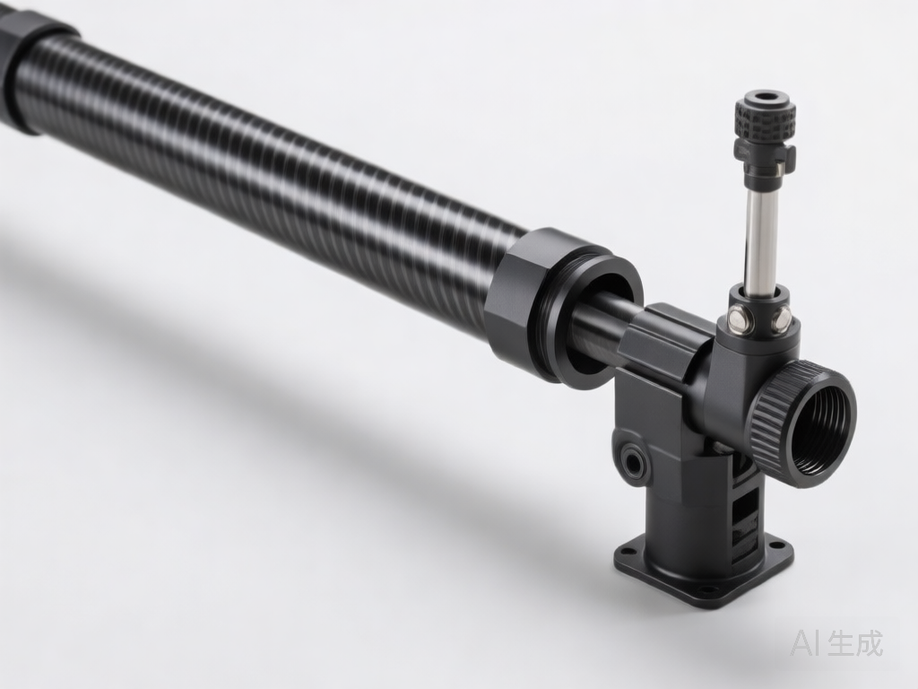
# Adjustable Length Carbon Tube Telescopic Sleeve Assembly: Design and Engineering Guide
## Introduction
In the pursuit of lightweight, high-performance structures, carbon fiber reinforced polymer (CFRP) tubes have become indispensable across aerospace, automotive, robotics, and consumer products. However, fixed-length carbon tubes often fall short when adaptability is required. The adjustable length carbon tube telescopic sleeve assembly solves this challenge by enabling precise, repeatable length variation while preserving the exceptional strength-to-weight ratio of carbon fiber. This article provides a comprehensive engineering overview of the design, materials, and assembly considerations for such systems, focusing exclusively on the telescopic sleeve assembly structure.
## Key Design Requirements
A well-engineered telescopic sleeve assembly must satisfy several critical requirements:
– **Adjustability**: Smooth, stepless length adjustment over a defined range.
– **Structural Integrity**: Maintain stiffness and load capacity under axial, bending, and torsional loads.
– **Lightweight**: Minimize added weight to leverage carbon fiber’s advantages.
– **Durability**: Resist wear, corrosion, and fatigue over repeated adjustment cycles.
– **Manufacturability**: Enable cost-effective production with tight tolerances.
These requirements drive the selection of materials, joint configurations, and locking mechanisms.
## Core Components of the Assembly
A typical adjustable carbon tube telescopic sleeve assembly comprises:
1. **Outer Carbon Tube**: The primary structural member, often with a larger diameter and thicker wall.
2. **Inner Carbon Tube**: Slides inside the outer tube; may have a smaller diameter and similar wall thickness.
3. **Sleeve or Collar**: A cylindrical component that bridges the two tubes and houses the locking mechanism. It can be made of carbon fiber, aluminum, or engineering polymers.
4. **Locking Mechanism**: Clamping, pinning, or friction-based system to secure the tubes at the desired length.
5. **End Fittings**: Connectors for attaching the assembly to other structures.
6. **Guide Rings/Bushings**: Optional components to ensure concentric alignment and smooth sliding.
## Structural Design Considerations
### Tube Fit and Tolerance
The clearance between the inner and outer tubes is critical. Too loose, and the assembly lacks rigidity; too tight, and adjustment becomes difficult or causes surface damage. A diametral clearance of 0.1–0.3 mm is typical for carbon-to-carbon interfaces, depending on surface finish and operating conditions. Precision machining or post-curing calibration of the tube ends may be necessary.
### Sleeve Geometry
The sleeve length and wall thickness influence the assembly’s bending stiffness and stress distribution. A longer sleeve reduces stress concentrations but adds weight. Finite element analysis (FEA) is recommended to optimize the sleeve’s profile, often incorporating fillets or tapers to smooth stress flow.
### Locking Mechanism Design
Several locking methods are employed:
– **Clamping**: A split collar with a bolt or cam lever compresses the outer tube onto the inner tube. This provides infinite adjustability and is user-friendly.
– **Pin Locking**: A spring-loaded pin engages holes drilled in the inner tube at discrete intervals. This offers high shear strength but limited positions.
– **Friction Lock**: Relies on interference fit or expanding elements (e.g., a wedge) to generate holding force. Requires careful design to prevent slippage.
Each method has trade-offs in terms of adjustability, load capacity, and complexity. Clamping is most common for carbon tubes due to its non-destructive nature.
### Surface Protection
Carbon fiber can be susceptible to abrasion and galvanic corrosion when in contact with metals. Protective coatings (e.g., polyurethane) or thin polymer liners on the sleeve’s inner surface can mitigate wear and isolate dissimilar materials.
## Material Selection
### Carbon Tubes
Standard modulus carbon fiber (e.g., T300, T700) with epoxy resin is typical. The layup sequence (e.g., [0/±45/90]s) should be tailored to the dominant load direction—unidirectional plies for axial stiffness, angle plies for torsional resistance. The outer surface may be sanded or coated to achieve a consistent friction coefficient.
### Sleeve Material
– **Carbon Fiber**: Offers the best weight-to-strength ratio but requires careful design to avoid galvanic issues and may be brittle under clamping forces.
– **Aluminum (6061-T6 or 7075-T6)**: Lightweight, machinable, and provides good clamping resilience. Anodizing improves wear resistance.
– **Engineering Polymers (e.g., POM, PEEK)**: Self-lubricating, corrosion-resistant, and gentle on carbon surfaces. Suitable for low-load applications.
### Locking Hardware
Stainless steel or titanium bolts and pins are common for corrosion resistance and strength. For weight-critical applications, titanium or aluminum hardware may be used.
## Assembly and Manufacturing Process
1. **Tube Fabrication**: Carbon tubes are produced via filament winding, roll wrapping, or pultrusion. Ends are cut and machined to precise dimensions.
2. **Sleeve Machining**: If metallic, the sleeve is CNC machined; if composite, it may be molded or machined from tube stock.
3. **Surface Preparation**: Bonding surfaces are abraded and cleaned; carbon surfaces may be primed.
4. **Bonding**: The sleeve is often bonded to the outer tube using structural epoxy adhesive. Bondline thickness (0.1–0.2 mm) is controlled with glass beads or scrim cloth.
5. **Assembly of Locking Mechanism**: Clamping collars, pins, or friction elements are installed and adjusted for proper function.
6. **Quality Control**: Inspections include dimensional checks, bond integrity (tap test or ultrasonic), and functional testing of the locking mechanism.
## Performance Testing and Validation
To ensure reliability, the following tests are recommended:
– **Axial Load Test**: Verify that the locking mechanism prevents slippage under tensile and compressive loads.
– **Bending Stiffness Test**: Measure deflection under transverse load to confirm rigidity.
– **Torsional Test**: Assess the assembly’s resistance to twisting.
– **Fatigue Test**: Simulate repeated adjustment cycles to evaluate wear and degradation.
– **Environmental Test**: Expose to temperature extremes, humidity, and salt spray to assess corrosion and material stability.
## Conclusion
The adjustable length carbon tube telescopic sleeve assembly is a sophisticated engineering solution that combines the lightweight strength of carbon fiber with the versatility of adjustable length. By carefully considering tube fit, sleeve geometry, locking mechanism, material selection, and manufacturing processes, designers can create assemblies that meet demanding performance criteria. As industries continue to seek adaptable, high-performance structures, this technology will play an increasingly vital role in the evolution of lightweight engineering.