
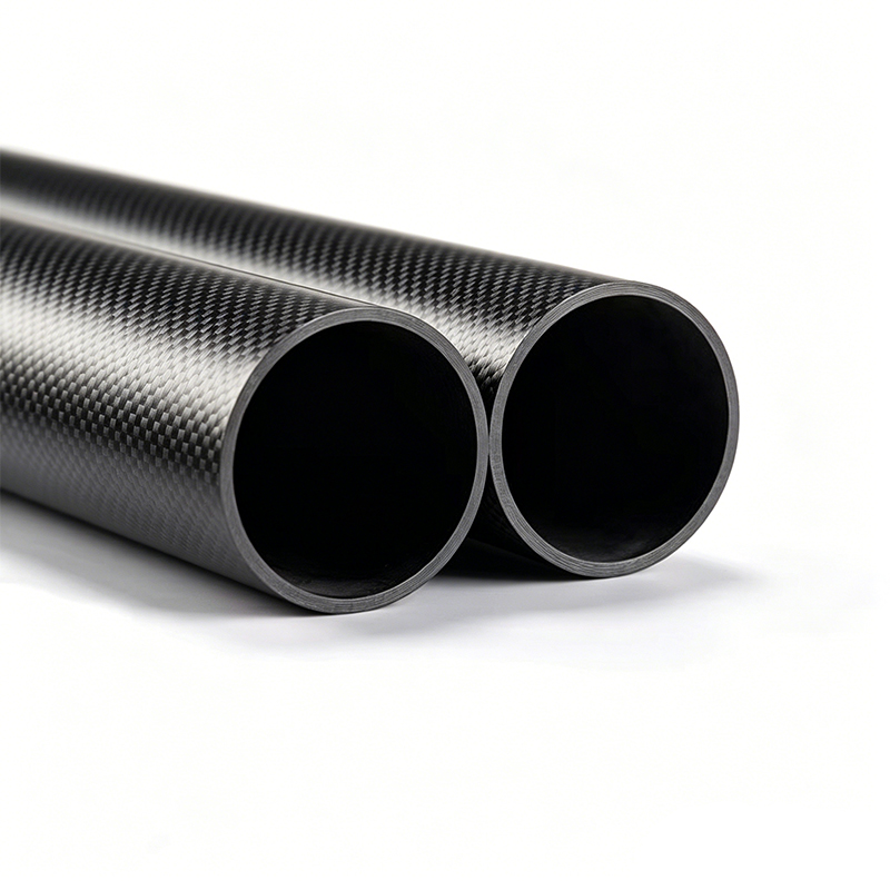
Introduction to Thermal Limits in Carbon Fiber Composites
Carbon fiber tubes are prized for their high strength-to-weight ratio, stiffness, and fatigue resistance. However, their performance in high-temperature environments is not defined by a single, universal number. The temperature resistance limit depends on the matrix system (the polymer resin that binds the fibers), the fiber type, and the duration of exposure. For engineering applications, this limit is a functional threshold—beyond which mechanical properties degrade irreversibly—rather than a melting point.
The Role of the Polymer Matrix
Bare carbon fibers themselves can withstand temperatures exceeding 2000°C in inert atmospheres. In practical tubes, however, the fibers are always embedded in a matrix, and that matrix dictates the thermal ceiling. Most commercially available carbon fiber tubes use one of three matrix systems:
- Epoxy resins (standard aerospace and automotive grade): These cure at 120–180°C and begin to soften at their glass transition temperature (Tg), typically 120–150°C. Prolonged exposure above Tg causes creep, delamination, and loss of compressive strength.
- BMI (bismaleimide) resins: Used for higher-performance applications, BMIs offer a Tg of 230–280°C, allowing short-term use up to 250°C.
- Polyimide and phenolic resins: These specialty systems push the limit to 300–400°C, but they are brittle and more expensive to process.
For a standard modulus epoxy tube, the safe continuous operating temperature is generally 100–180°C. Short-term spikes (minutes) may reach 200°C, but repeated cycling will rapidly degrade interlaminar shear strength (ILSS).
Testing Protocols for Thermal Stability
Material stability testing in high-temperature environments is standardized to simulate real-world service. Two key tests are used:
- Dynamic Mechanical Analysis (DMA) – Measures storage modulus and tan delta as temperature ramps up. The peak of tan delta defines Tg. For epoxy tubes, Tg typically ranges from 130°C to 180°C depending on the cure cycle. Data from DMA is critical because it shows both the elastic response (load-bearing ability) and the damping (energy dissipation), which changes sharply as the matrix softens.
- Thermogravimetric Analysis (TGA) – Measures mass loss during controlled heating. A stable tube should show less than 5% weight loss up to 300°C in air for epoxy systems. Above 300°C, oxidative degradation begins, causing the resin to char and release volatiles. For BMI tubes, the onset of significant weight loss is shifted to ~400°C.
- Interlaminar Shear Strength (ILSS) Testing After Heat Aging – Samples are exposed to a target temperature (e.g., 150°C, 200°C, 250°C) for 100, 500, or 1000 hours, then tested at room temperature. A common acceptance criterion is retaining at least 70% of the original ILSS. For standard epoxy, this retention is achieved only up to 150°C. At 200°C, most epoxies retain 40–50% after 500 hours.
Quantitative Limits for Common Configurations
Based on published data from composite manufacturers and research papers, the following are representative limits for continuous use:
- Epoxy-based tubes: 120–150°C continuous; 180°C for less than 10 minutes; no reliable structural use above 200°C.
- BMI-based tubes: 220–250°C continuous; short-term exposure up to 300°C (minutes); Tg around 260°C.
- Polyimide-based tubes: 300–350°C continuous; short excursions to 400°C possible, but oxidative resistance in air is limited.
- Phenolic-based tubes: 200–250°C continuous with excellent fire resistance, but they absorb moisture and have lower shear strength.
Crucially, compression strength and modulus drop faster than tensile strength as temperature approaches Tg. This is because the resin matrix is primarily responsible for supporting compressive loads and preventing fiber microbuckling.
Environmental Factors Beyond Temperature
Thermal limits are not absolute—they interact with environment:
- Oxidative atmosphere: In air above 250°C, carbon fibers undergo oxidation at surface defects, leading to pitting and strength loss. Nitrogen or vacuum environments raise the usable temperature by 100–150°C.
- Thermal cycling: Rapid cycling between room temperature and 150°C induces microcracks due to coefficient of thermal expansion (CTE) mismatch between fiber (-0.5 ppm/°C longitudinal) and resin (30–50 ppm/°C). This mechanical fatigue may lower the effective limit by 20–30°C compared to isothermal exposure.
- Load state: A tube under sustained bending or torsion will creep more at lower temperatures than an unloaded tube. Design allowables should derate the temperature limit by 15–20°C when non-negligible static stresses are present.
Practical Guidance for Design Engineers
To select a carbon fiber tube for high-temperature service:
- Request the manufacturer’s Tg from DMA (not just the advertised "service temperature").
- Apply a safety factor: continuous operating temperature should be at least 30°C below Tg for structural reliability.
- If the application exceeds 180°C, do not assume an offset weave or high-modulus fiber solves the problem—the matrix remains the bottleneck.
- For future needs, consider post-curing epoxies at 180–200°C to raise Tg by 20–40°C, but verify that this does not introduce microcracks in thick walls.
Conclusion
The temperature resistance limit of a carbon fiber tube is a system property, not a fiber property. For standard epoxy tubes, the practical ceiling is 150°C continuous; for BMI, 250°C; and for polyimides, 350°C. Material stability testing—particularly DMA and heat-aging ILSS—must be performed at the exact expected service temperature and atmosphere. Above these limits, the tube will not melt but will undergo progressive matrix softening, microcracking, and oxidative damage that ultimately compromises structural integrity. Always validate with actual test data, and design with a thermal margin that matches the load and lifetime requirements.