
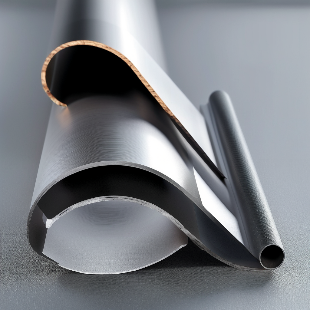
## Introduction
Carbon fiber tubes are celebrated for their exceptional strength-to-weight ratio, making them indispensable in aerospace, automotive, robotics, and sporting goods. However, one of the most common engineering pitfalls is selecting a wall thickness that is either too thin (risking failure) or excessively thick (adding weight and cost without benefit). This article provides a systematic approach to choosing the optimal carbon fiber tube wall thickness by precisely matching load requirements, thereby avoiding over-design and ensuring structural efficiency.
## Understanding Load Types and Their Impact on Wall Thickness
Before diving into thickness calculations, it is crucial to identify the type of load the tube will experience. The primary load modes include:
– **Axial Tension/Compression:** Uniform stress across the cross-section. Wall thickness directly influences the cross-sectional area and thus the load capacity.
– **Bending:** Creates a stress gradient, with maximum stress at the outer and inner surfaces. Thicker walls increase the moment of inertia, enhancing bending stiffness.
– **Torsion:** Shear stress distribution is highest at the outer surface. Wall thickness affects the polar moment of inertia.
– **Buckling:** Under compressive or bending loads, thin-walled tubes can fail by buckling before material yield. Wall thickness is critical for buckling resistance.
Each load type demands a different thickness calculation, and real-world applications often involve combined loads, requiring a multi-axial stress analysis.
## Key Material Properties of Carbon Fiber Composites
Unlike isotropic metals, carbon fiber composites are anisotropic—their properties vary with fiber orientation. For tubes, fibers are typically oriented along the axis (0°) for bending/axial loads, with some ±45° layers for torsion and hoop strength. Key properties include:
– **Tensile Modulus (E):** Ranges from 100 GPa (standard) to 300+ GPa (high modulus).
– **Tensile Strength (σ):** Typically 600–2000 MPa depending on fiber type and resin system.
– **Compressive Strength:** Often lower than tensile, especially in thin laminates.
– **Interlaminar Shear Strength (ILSS):** Critical for avoiding delamination under bending or impact.
These properties are direction-dependent, so the laminate stacking sequence must be considered when calculating thickness.
## Step-by-Step Thickness Selection Process
### 1. Define Load Requirements and Safety Factors
Start by quantifying the maximum expected loads (force, moment, torque) and the allowable deflection or strain. Apply an appropriate safety factor (typically 1.5–2.5 for static loads, higher for fatigue or impact). This gives the design load.
### 2. Calculate Required Cross-Sectional Properties
For a tube with outer diameter (D) and wall thickness (t), the cross-sectional area (A) is:
A = π/4 * (D² – (D-2t)²)
For bending, the moment of inertia (I) is:
I = π/64 * (D⁴ – (D-2t)⁴)
For torsion, the polar moment of inertia (J) is:
J = π/32 * (D⁴ – (D-2t)⁴)
Using these, you can determine the minimum thickness to keep stress below the allowable limit. For example, for axial load P, the required area is A_req = P / (σ_allowable). Then solve for t.
### 3. Check Buckling Resistance
Thin-walled tubes under compression or bending can buckle. Use Euler’s buckling formula for long columns:
P_cr = π²EI / (KL)²
where K is the column effective length factor. For local buckling (crippling), empirical formulas exist based on D/t ratio. A common rule of thumb is to keep D/t < 30 for structural tubes to avoid local instability. ### 4. Consider Manufacturing Constraints Carbon fiber tubes are typically produced by pultrusion, roll wrapping, or filament winding. Minimum wall thickness is often limited by the manufacturing process (e.g., 0.5 mm for pultrusion, 1 mm for roll wrapping). Also, resin content and fiber volume fraction affect mechanical properties—higher fiber volume (60–65%) yields better strength but may reduce toughness. ### 5. Optimize for Weight and Cost Once a minimum thickness is established, evaluate whether increasing thickness adds meaningful performance. Over-design occurs when thickness is increased without a corresponding load requirement, leading to unnecessary weight and material cost. Use finite element analysis (FEA) to refine the design and identify stress concentrations. ## Common Mistakes and How to Avoid Them – **Ignoring Combined Loads:** A tube may be subjected to bending and torsion simultaneously. Use von Mises stress criteria for combined stress states. – **Using Only Tensile Strength:** Compressive strength of carbon fiber composites is often lower; verify both. – **Neglecting Impact Resistance:** Thin walls may be susceptible to impact damage. If impact is a concern, increase thickness or add protective layers. – **Overestimating Material Properties:** Data from material datasheets are for ideal conditions. Apply knockdown factors for environmental effects (moisture, temperature). ## Case Study: Selecting Wall Thickness for a Drone Arm Consider a drone arm that must support a 2 kg payload at a 300 mm distance, creating a bending moment of 5.88 Nm. The arm is a 20 mm outer diameter carbon fiber tube. Using a safety factor of 2, the design moment is 11.76 Nm. With a bending stress allowable of 400 MPa (typical for high-strength carbon fiber), the required section modulus is: S = M / σ = 11.76 / 400e6 = 2.94e-5 m³ For a tube, S = I / (D/2). Solving for t gives approximately 1.2 mm. However, checking buckling for a 300 mm length with D/t = 16.7, which is safe. Thus, a 1.5 mm wall thickness would be a balanced choice, avoiding over-design while providing a safety margin. ## Conclusion Selecting the correct carbon fiber tube wall thickness is a balance between structural integrity and weight efficiency. By systematically analyzing load types, calculating required cross-sectional properties, and considering manufacturing and environmental factors, engineers can precisely match thickness to application demands. This approach prevents over-design, reduces material waste, and ensures optimal performance. Always validate calculations with prototyping and testing, as real-world conditions may reveal nuances not captured in theoretical models. For critical applications, consult with composite material specialists and leverage FEA to refine the design. Remember, the goal is not the thickest tube, but the right thickness for the job.