
## Introduction
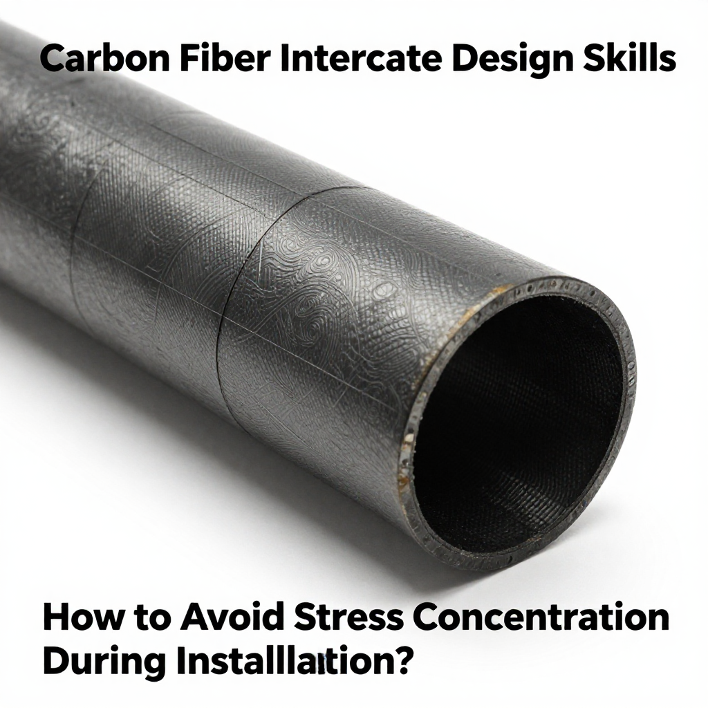
Carbon fiber tubes are widely used in aerospace, automotive, robotics, and sporting goods due to their high strength-to-weight ratio and stiffness. However, their anisotropic nature makes them particularly sensitive to localized stresses. During installation, improper interface design can lead to stress concentration, causing premature failure, delamination, or cracking. This article provides practical design skills to minimize stress concentration at carbon fiber tube interfaces, ensuring reliable performance and longevity.
## Understanding Stress Concentration in Carbon Fiber Tubes
Stress concentration occurs when stress is amplified at geometric discontinuities such as holes, notches, sharp corners, or abrupt changes in cross-section. For carbon fiber composites, which have relatively low interlaminar shear strength, stress concentration can trigger delamination or fiber breakage. During installation, common sources include:
– Press-fit or interference fits
– Bolted or riveted connections
– Adhesive bonding with mismatched stiffness
– Clamping forces from collars or fittings
## Key Design Principles for Interface Geometry
### Avoid Sharp Edges and Corners
Sharp transitions create high stress gradients. Design interfaces with generous fillets or radii. For example, when a metal fitting is bonded to a carbon tube, the edge of the adhesive joint should be tapered or feathered to reduce peel stress.
### Use Gradual Cross-Section Changes
If the tube must connect to a larger or smaller diameter component, use a tapered transition over a length at least 3–5 times the tube diameter. This spreads the load and reduces stress concentration.
### Optimize Overlap Length in Bonded Joints
The overlap length in adhesive joints directly affects stress distribution. Too short an overlap causes high peak stresses; too long may not improve strength significantly. A typical rule is an overlap length of 10–20 times the tube wall thickness. Finite element analysis (FEA) can help determine the optimal value.
## Selecting the Right Connection Method
### Adhesive Bonding vs. Mechanical Fastening
Adhesive bonding distributes load over a larger area, reducing stress concentration compared to mechanical fasteners that create localized point loads. However, bonding requires careful surface preparation and adhesive selection. Mechanical fasteners (bolts, pins) should be avoided unless absolutely necessary, as drilling holes in carbon fiber tubes severely weakens them and creates stress raisers.
### Press-Fit and Interference Fit Considerations
Press-fitting a metal insert into a carbon tube can generate high radial stresses. To avoid stress concentration, use a tapered insert or a split sleeve to allow gradual load transfer. Alternatively, use a shrink-fit with controlled temperature to reduce assembly forces.
## Surface Preparation and Tolerance Control
### Surface Roughness and Cleanliness
Proper surface preparation is critical for adhesive bonding. The tube surface should be lightly abraded and cleaned with a solvent to remove contaminants. Avoid deep scratches that can act as crack initiators.
### Tolerance and Clearance
Tight tolerances can cause uneven contact and stress peaks. Design with a controlled clearance (e.g., 0.05–0.1 mm) for adhesive joints to ensure uniform bond line thickness. For mechanical connections, use precision-machined parts with matched tolerances to avoid point loading.
## Load Transfer and Stress Distribution Techniques
### Use of Load Introduction Elements
Incorporate load introduction elements such as tapered sleeves, gussets, or collars that gradually transfer load from the tube to the connecting part. For example, a metal end fitting with a tapered internal bore can distribute clamping force over a larger area.
### Stress-Relief Grooves and Slots
In some cases, adding a stress-relief groove at the end of a bonded joint can reduce peel stress. However, this must be done carefully to avoid creating new stress raisers. FEA is recommended to validate the design.
### Consideration of Thermal Expansion Mismatch
Carbon fiber has a near-zero coefficient of thermal expansion, while metals expand significantly. In environments with temperature variations, differential expansion can induce stress at the interface. Use compliant adhesive layers or design with a flexible intermediate material to accommodate thermal movement.
## Installation Process Guidelines
### Controlled Assembly Force
During installation, avoid excessive force that can cause local crushing or delamination. Use torque limiters or pressure-sensitive adhesives to control the assembly process.
### Alignment and Fixturing
Misalignment during installation can cause uneven loading. Use alignment fixtures or guides to ensure the tube and fitting are coaxial. For bonded joints, use spacers to maintain uniform bond line thickness.
### Curing and Post-Curing
For adhesive bonding, follow the manufacturer’s curing schedule. Apply uniform pressure during curing to prevent voids and ensure consistent bond quality. Post-curing may be necessary to achieve full strength.
## Testing and Validation
After installation, perform non-destructive testing (NDT) such as ultrasonic inspection or X-ray to detect voids or delamination. Mechanical testing on sample assemblies can verify that stress concentration is within acceptable limits.
## Conclusion
Avoiding stress concentration during the installation of carbon fiber tubes requires a holistic approach that includes thoughtful interface geometry, appropriate connection methods, precise surface preparation, and controlled assembly processes. By implementing the design skills outlined in this article, engineers can significantly reduce the risk of premature failure and ensure the structural integrity of carbon fiber tube assemblies. Always validate designs with FEA and physical testing to achieve optimal performance.