
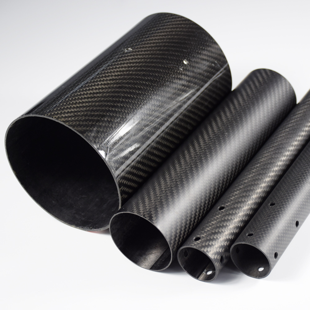
## Introduction
Carbon fiber tubes are celebrated for their exceptional strength-to-weight ratio, making them indispensable in aerospace, automotive, robotics, and sporting goods. However, one of the most common engineering pitfalls is selecting a wall thickness that is either too thin (risking failure) or unnecessarily thick (adding weight and cost). This article provides a systematic approach to choosing the optimal carbon fiber tube wall thickness by precisely matching load requirements, thereby avoiding over-design and maximizing performance.
## Understanding Load Types and Their Impact on Wall Thickness
Before selecting a wall thickness, engineers must identify the primary load types the tube will experience. Each load case imposes different stress distributions, which directly influence the required wall thickness.
### Axial Tension and Compression
Axial loads act along the tube’s length. In tension, the entire cross-section carries the load uniformly. In compression, failure can occur by buckling rather than material crushing, especially for thin-walled tubes. For compression-dominated applications, wall thickness must be sufficient to prevent local buckling, which is governed by the tube’s diameter-to-thickness ratio (D/t). A lower D/t (thicker wall) increases buckling resistance.
### Bending Loads
Bending creates tensile and compressive stresses on opposite sides of the tube. The maximum stress occurs at the outer fibers. Increasing wall thickness raises the moment of inertia, thereby reducing stress for a given bending moment. However, for large-diameter tubes, even a modest increase in wall thickness can significantly boost bending stiffness without excessive weight gain.
### Torsional Loads
Torsion (twisting) generates shear stresses that are highest at the outer surface. Thin-walled tubes are efficient in torsion because shear stress is nearly constant across the wall. However, if the wall is too thin, the tube may suffer from torsional buckling or excessive twist. A balanced wall thickness ensures adequate torsional rigidity while keeping weight low.
### Combined Loads
Real-world applications often involve combined loads (e.g., bending plus torsion). In such cases, engineers must use failure criteria like Tsai-Wu or maximum stress theory to evaluate the interaction. A wall thickness that satisfies individual loads may not be sufficient for combined loading, so a more robust analysis is required.
## Material Properties and Laminate Orientation
Carbon fiber tubes are anisotropic; their mechanical properties depend on fiber orientation. The wall thickness alone does not determine performance—fiber layup is equally critical.
### Unidirectional vs. Multi-Directional Laminates
– **Unidirectional (UD) fibers** aligned along the tube axis provide maximum axial strength and stiffness but are weak in hoop (circumferential) direction.
– **Multi-directional laminates** (e.g., ±45° and 90° plies) offer balanced properties, improving resistance to torsion and internal pressure.
When selecting wall thickness, consider the laminate schedule. For axial loads, a thinner wall with UD fibers may suffice. For pressure vessels or torsion, additional hoop plies are necessary, which increases the required wall thickness.
### Ply Thickness and Stacking Sequence
Each carbon fiber prepreg ply has a standard cured thickness (typically 0.1–0.2 mm). The total wall thickness is the sum of individual plies. The stacking sequence affects interlaminar shear strength and impact resistance. A thicker wall with more plies can be tailored to meet specific load requirements, but over-stacking leads to unnecessary weight.
## Calculating Required Wall Thickness
A step-by-step calculation ensures precision and avoids over-design.
### Step 1: Define Load and Safety Factor
Determine the maximum expected load (force, moment, torque) and apply an appropriate safety factor (typically 1.5–2.5 depending on industry standards).
### Step 2: Determine Allowable Stress
Use the material’s allowable stress (ultimate or yield) from the laminate properties. For carbon fiber, ultimate tensile strength can range from 600 MPa to over 2000 MPa, depending on fiber type and resin system.
### Step 3: Calculate Required Cross-Sectional Area
For axial tension: \( A = F / (\sigma_{allow}) \), where \( F \) is the applied force and \( \sigma_{allow} \) is allowable stress. The wall thickness \( t \) can then be derived from the cross-sectional area of a hollow tube: \( A = \pi (D_o^2 – D_i^2)/4 \), where \( D_o \) and \( D_i \) are outer and inner diameters.
### Step 4: Check Buckling for Compression and Bending
For compression, use Euler’s buckling formula or local buckling charts. For bending, ensure the bending stress \( \sigma = M \cdot c / I \) is below allowable, where \( c \) is the distance from neutral axis to outer fiber and \( I \) is the second moment of area.
### Step 5: Iterate with Laminate Design
Adjust the number of plies and orientations to meet the calculated thickness while considering manufacturability and cost.
## Avoiding Over-Design: Weight and Cost Implications
Over-design occurs when wall thickness is larger than necessary, leading to:
– **Increased weight**: Carbon fiber is expensive per kilogram; extra material adds cost and reduces performance in weight-sensitive applications.
– **Higher material cost**: Thicker walls consume more prepreg, increasing raw material expenses.
– **Manufacturing challenges**: Thicker laminates may require longer cure cycles and more complex tooling.
To avoid over-design, engineers should:
– Use finite element analysis (FEA) to validate thickness choices under realistic loading.
– Consider hybrid designs, such as using foam cores or ribs to increase stiffness without adding wall thickness.
– Optimize the laminate schedule to place material where it is most effective.
## Practical Tips for Wall Thickness Selection
– **Start with standard thicknesses**: Many manufacturers offer tubes with standard wall thicknesses (e.g., 1mm, 1.5mm, 2mm). Choose the nearest standard that meets requirements to reduce cost.
– **Prototype and test**: Physical testing under actual load conditions is the ultimate validation. Use strain gauges to measure deformation and compare with predictions.
– **Consider environmental factors**: Moisture and temperature can degrade carbon fiber properties. Apply a safety margin if the tube will be exposed to harsh environments.
– **Consult with manufacturers**: Experienced carbon fiber tube suppliers can provide guidance on achievable tolerances and laminate options.
## Case Study: Selecting Wall Thickness for a Drone Arm
A drone arm must withstand bending loads from motor thrust and vibration. The arm is a 20 mm outer diameter tube with a length of 300 mm. The maximum bending moment is 50 N·m. Using a carbon fiber laminate with an allowable bending stress of 400 MPa, the required section modulus is \( S = M / \sigma = 50 / 400e6 = 1.25e-7 \) m³. For a hollow tube, \( S = \pi (D_o^4 – D_i^4) / (32 D_o) \). Solving for \( D_i \) gives an inner diameter of about 18 mm, resulting in a wall thickness of 1 mm. However, to account for dynamic loads and a safety factor of 2, the wall thickness is increased to 1.5 mm. This avoids over-design while ensuring reliability.
## Conclusion
Selecting the correct carbon fiber tube wall thickness is a balance between structural integrity and weight efficiency. By thoroughly analyzing load types, understanding material properties, and performing precise calculations, engineers can avoid over-design and achieve optimal performance. Remember that wall thickness is not the only variable—laminate orientation and stacking sequence play equally important roles. Always validate your design through testing and collaborate with material suppliers to ensure manufacturability. With these skills, you can confidently specify carbon fiber tubes that meet exact load requirements without unnecessary bulk.
## References
– Carbon Fiber Tube Manufacturer Guidelines
– Composite Materials Handbook (CMH-17)
– Finite Element Analysis in Composite Structures