
## Introduction
Carbon fiber reinforced polymer (CFRP) tubes have become a staple in high-performance industries such as aerospace, robotics, automotive, and sporting goods due to their exceptional strength-to-weight ratio and stiffness. When these tubes require integration into larger assemblies, threaded ends offer a reliable, removable, and high-strength connection method. However, procuring customized threaded carbon fiber tubes for bolt assembly structures is not as straightforward as ordering standard metal rods. This guide provides a comprehensive overview of the critical technical, manufacturing, and procurement considerations to ensure your threaded CFRP tubes meet performance, durability, and cost requirements.
## Understanding Threaded Carbon Fiber Tubes
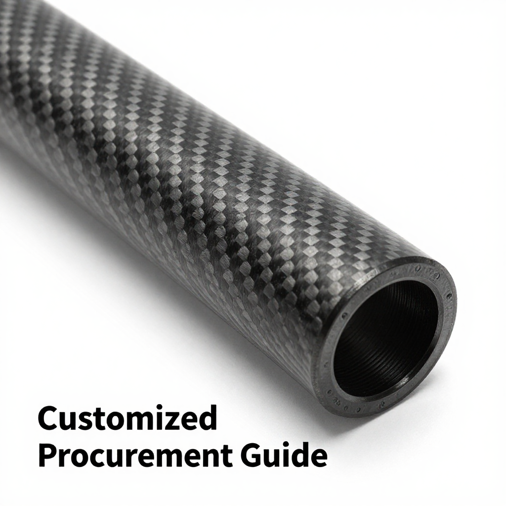
Threaded carbon fiber tubes are cylindrical components manufactured from unidirectional or woven carbon fiber layers, with machined or molded threads at one or both ends. These threads allow the tube to be bolted directly to mating metal or composite parts, eliminating the need for separate threaded inserts or adhesive bonding. The threads can be external (male) or internal (female), depending on the application.
### Why Use Threaded CFRP Tubes?
– **Weight Reduction:** Up to 70% lighter than equivalent steel or aluminum components.
– **High Strength:** Excellent tensile and compressive strength along the fiber direction.
– **Corrosion Resistance:** Inherently resistant to environmental degradation.
– **Design Flexibility:** Customizable length, diameter, layup, and thread type.
## Key Design Considerations for Threaded CFRP Tubes
### 1. Thread Geometry and Standards
Threads on carbon fiber tubes are typically machined after curing, but the geometry must be carefully selected to avoid stress concentrations that can lead to delamination. Common thread standards include:
– **Metric (ISO)** – e.g., M10x1.5
– **Unified (UNC/UNF)** – e.g., 1/4-20
– **Custom profiles** – for specialized applications
**Important:** The thread length should be at least 1.5 times the tube diameter to ensure adequate load distribution. Coarse threads are generally preferred over fine threads because they reduce the risk of thread stripping in composite materials.
### 2. Fiber Orientation and Layup
To maximize thread strength, the carbon fiber layers must be oriented to handle the shear and bearing loads imposed by the threads. A typical layup includes:
– **±45° layers** – to resist torsion and shear during bolt tightening.
– **0° layers** – to provide axial stiffness and strength.
– **90° layers** – to improve radial strength and prevent splitting.
A balanced symmetric layup is recommended to avoid warping during curing. The use of high-modulus fibers may increase stiffness but can reduce thread toughness; therefore, intermediate modulus fibers are often a better choice for threaded sections.
### 3. Wall Thickness and Thread Engagement
Sufficient wall thickness is critical to accommodate thread depth without compromising the tube’s structural integrity. A minimum wall thickness of 2.5 mm is advised for most applications, but thicker walls may be required for high-load scenarios. The thread engagement length (the portion of the bolt that actually contacts the tube threads) must be calculated based on the shear strength of the composite material. Typically, engagement length should be at least 1.2 times the bolt diameter.
### 4. Tolerances and Fit
Carbon fiber composites have a higher coefficient of thermal expansion (CTE) mismatch with metal bolts, which can affect thread fit under temperature variations. Therefore, tolerances must be specified carefully. A class 6H/6g fit (ISO) is common, but for applications with extreme temperature changes, a looser fit may be necessary to prevent binding or stress locking.
## Manufacturing Processes for Threaded CFRP Tubes
### 1. Filament Winding
Filament winding is the most common method for producing continuous fiber tubes. Fibers are wound around a mandrel in a precise pattern, then cured. Threads can be formed by:
– **Machining after cure** – using CNC lathes with diamond tooling.
– **Molding** – using a threaded mandrel that creates threads during curing (less common due to complexity).
### 2. Pultrusion
Pultrusion produces constant cross-section profiles with unidirectional fibers. Threads are typically machined after pultrusion. This method is cost-effective for high-volume production but offers less flexibility in fiber orientation.
### 3. Roll Wrapping
Roll wrapping involves wrapping prepreg sheets around a mandrel. It allows for precise control of fiber orientation and is suitable for custom layups. Threads are machined after curing.
### 4. Machining Threads
Threading CFRP requires specialized tooling and techniques:
– **Diamond-coated tools** – for extended tool life and clean cuts.
– **Low feed rates** – to minimize delamination.
– **Peck drilling** – for internal threads to evacuate chips.
– **Coolant** – to reduce heat buildup, which can degrade the resin.
## Customization Options
### 1. Tube Dimensions
– **Outer diameter:** from 5 mm to over 200 mm.
– **Wall thickness:** from 1 mm to 15 mm.
– **Length:** up to 6 meters (longer lengths may require splicing).
### 2. Thread Types
– **External threads** – for bolting into a female receiver.
– **Internal threads** – for accepting a bolt or stud.
– **Double-ended threads** – for connecting two components.
### 3. End Configurations
– **Plain ends** – for custom machining.
– **Threaded ends** – with or without a shoulder.
– **Threaded inserts** – metallic inserts bonded or molded into the tube (alternative to direct threading).
### 4. Surface Finish
– **Matte or gloss** – depending on aesthetic requirements.
– **Protective coatings** – such as polyurethane or epoxy for UV resistance.
– **Anti-wear treatments** – for threaded areas to reduce friction and wear.
## Quality Control and Testing
### 1. Dimensional Inspection
– **Thread pitch and profile** – using thread gauges.
– **Tube straightness** – within 0.5 mm per meter.
– **Wall thickness uniformity** – via ultrasonic testing.
### 2. Mechanical Testing
– **Tensile test** – to verify axial strength.
– **Compression test** – to check crush resistance.
– **Torque test** – to ensure threads can withstand specified tightening torque without stripping.
– **Fatigue test** – for cyclic loading applications.
### 3. Non-Destructive Testing (NDT)
– **Ultrasonic scanning** – to detect internal voids or delaminations.
– **X-ray inspection** – for critical aerospace components.
## Procurement Checklist
When requesting quotes from suppliers, provide the following information:
1. **Application details** – including expected loads, environment, and temperature range.
2. **Tube dimensions** – OD, ID, wall thickness, and length.
3. **Thread specification** – standard, size, pitch, and class.
4. **Layup requirements** – fiber type, resin system, and orientation.
5. **Quantity** – prototype vs. production volumes.
6. **Certifications** – e.g., AS9100, ISO 9001.
7. **Lead time** – typical is 4-8 weeks for custom orders.
## Common Pitfalls to Avoid
– **Underestimating thread stress** – always perform a torque analysis.
– **Choosing too fine a thread pitch** – increases risk of stripping.
– **Ignoring thermal expansion** – can cause thread binding.
– **Selecting a supplier without composite threading experience** – always ask for samples.
## Conclusion
Threaded carbon fiber tubes offer a lightweight and robust solution for bolt assembly structures, but their successful implementation requires careful design, precise manufacturing, and rigorous quality control. By understanding the key parameters—thread geometry, fiber layup, wall thickness, and tolerances—you can effectively communicate your needs to suppliers and ensure that the final product meets your performance expectations. Use this guide as a reference during your procurement process to avoid common mistakes and achieve a reliable, high-quality threaded CFRP tube for your specific application.