
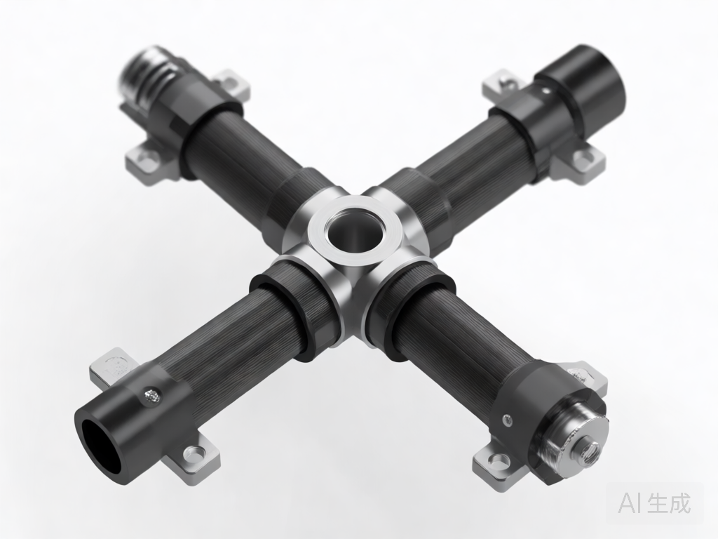
# Multi-Way Carbon Tube Cross Joint Structural Design for Equipment Brackets
## Introduction
In the realm of advanced engineering, equipment brackets are critical components that provide structural support, alignment, and stability for a wide range of machinery and devices. As industries demand lighter, stronger, and more corrosion-resistant solutions, carbon fiber reinforced polymer (CFRP) tubes have emerged as a preferred material. Among the various configurations, multi-way carbon tube cross joints play a pivotal role in creating complex, load-bearing frameworks. This article delves into the structural design considerations, challenges, and best practices for multi-way carbon tube cross joints specifically tailored for equipment brackets.
## Why Carbon Fiber for Equipment Brackets?
Carbon fiber composites offer an exceptional strength-to-weight ratio, high stiffness, and excellent fatigue resistance. Unlike metals, they do not rust and can be engineered to have tailored directional properties. For equipment brackets, these attributes translate to reduced inertial loads, easier installation, and long-term durability in harsh environments. However, designing joints that effectively transfer loads between multiple carbon tubes remains a significant engineering challenge.
## Understanding Multi-Way Cross Joints
A multi-way cross joint connects three or more carbon tubes at a single node, typically at angles that are not necessarily orthogonal. In equipment brackets, such joints are used to create space frames, trusses, and mounting platforms. The joint must distribute axial, bending, and torsional loads without causing stress concentrations that could lead to delamination or fiber failure.
### Types of Multi-Way Joints
– **T-joints:** Connect three tubes at 90 degrees.
– **X-joints:** Connect four tubes in a cross pattern.
– **Y-joints:** Connect three tubes at non-90-degree angles.
– **Custom multi-port joints:** Designed for specific bracket geometries with five or more tubes.
Each type requires a unique design approach to ensure structural integrity.
## Key Structural Design Considerations
### 1. Load Path and Stress Distribution
The primary function of a cross joint is to transfer loads between tubes. The design must ensure that forces flow smoothly from one tube to another without abrupt changes in stiffness. Finite element analysis (FEA) is essential to visualize stress concentrations and optimize the joint geometry. Critical areas include the bond lines, fillets, and any metallic inserts.
### 2. Material Selection and Compatibility
Carbon fiber tubes are anisotropic, meaning their properties vary with direction. The joint material—whether carbon composite, titanium, aluminum, or engineering polymers—must have a coefficient of thermal expansion (CTE) compatible with the tubes to minimize thermal stresses. Additionally, galvanic corrosion must be considered when metals are used with carbon fiber.
### 3. Joining Methods
Several methods are employed to create multi-way joints:
– **Adhesive bonding:** Uses high-strength epoxy adhesives. It distributes stress uniformly but requires careful surface preparation and cure control.
– **Mechanical fastening:** Involves bolts, rivets, or pins. It allows disassembly but creates stress concentrations and requires holes that can cut fibers.
– **Co-curing/co-bonding:** The joint is formed simultaneously with the tubes in a mold, creating a seamless structure. This method offers the best load transfer but is complex and costly.
– **Hybrid joints:** Combine adhesive bonding with mechanical fasteners for redundancy and improved damage tolerance.
### 4. Geometric Design
The geometry of the joint—including wall thickness, fillet radii, and taper angles—significantly affects performance. Sharp corners should be avoided to reduce stress concentrations. Fillets and chamfers help distribute loads more evenly. The use of metallic inserts or sleeves can reinforce the joint area and provide a reliable interface for fasteners.
### 5. Failure Modes and Safety Factors
Common failure modes for multi-way carbon tube joints include adhesive debonding, delamination, fiber breakage, and buckling. Designers must apply appropriate safety factors based on the criticality of the application and the variability of loads. Non-destructive testing (NDT) methods such as ultrasonic inspection or X-ray computed tomography can verify joint integrity.
## Design Process for Multi-Way Cross Joints
A systematic approach ensures optimal performance:
1. **Define requirements:** Load cases, stiffness targets, environmental conditions, and weight constraints.
2. **Conceptual design:** Sketch joint configurations and select joining methods.
3. **Material selection:** Choose tube and joint materials based on mechanical and thermal properties.
4. **Detailed design:** Use CAD and FEA to optimize geometry and validate stress levels.
5. **Prototype and test:** Manufacture a prototype and perform static and fatigue tests.
6. **Iterate:** Refine the design based on test results.
## Case Study: Equipment Bracket for Aerospace Ground Support
A ground support equipment bracket required a lightweight, multi-way joint connecting four carbon tubes at varying angles. The original aluminum bracket was heavy and prone to fatigue cracks. The redesigned joint used a co-cured carbon fiber node with titanium inserts for bolted connections. FEA showed a 40% reduction in peak stresses, and physical testing confirmed a 60% weight saving while exceeding the required load capacity.
## Best Practices for Multi-Way Carbon Tube Cross Joints
– **Avoid abrupt changes in stiffness:** Taper tube ends and use gradual transitions.
– **Use adhesive bonding with mechanical redundancy:** This combination provides reliability.
– **Incorporate fillets and radii:** Reduce stress concentrations.
– **Consider environmental factors:** UV radiation, moisture, and temperature extremes can degrade adhesives and composites.
– **Validate with testing:** Always test prototypes under realistic load conditions.
## Conclusion
Multi-way carbon tube cross joints are indispensable for modern equipment brackets, offering unmatched weight savings and performance. However, their design demands careful consideration of load paths, material compatibility, joining methods, and failure modes. By following a systematic design process and leveraging advanced analysis and testing, engineers can create robust, efficient joints that meet the most demanding applications. As carbon fiber technology continues to evolve, we can expect even more innovative joint designs that push the boundaries of what is possible in equipment bracket engineering.