
## Introduction
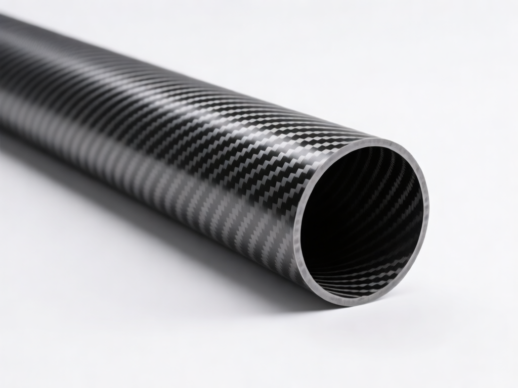
Thin-wall carbon fiber tubes are increasingly used in aerospace, automotive, and high-performance sporting goods due to their exceptional strength-to-weight ratio. However, achieving precise dimensional tolerances after post-processing is a significant challenge. The inherent flexibility of thin walls, coupled with the abrasive nature of carbon fiber, makes tolerance control a critical manufacturing concern. This article explores the key factors, techniques, and best practices for post-processing dimensional tolerance control of thin-wall carbon fiber tubes.
## Understanding the Challenges
Thin-wall carbon fiber tubes typically have wall thicknesses ranging from 0.5 mm to 2 mm. Their low stiffness makes them prone to deflection during machining, leading to dimensional errors. Additionally, carbon fiber’s anisotropic properties and abrasive characteristics accelerate tool wear, further complicating tolerance control. Common post-processing operations include trimming, drilling, and surface grinding, each introducing unique challenges.
## Key Factors Affecting Dimensional Tolerance
### 1. Material Properties
Carbon fiber reinforced polymer (CFRP) exhibits directional strength and thermal expansion. The coefficient of thermal expansion (CTE) varies along and across fibers, causing uneven expansion during machining. This can lead to residual stresses and dimensional instability.
### 2. Tooling and Machining Parameters
Tool geometry, feed rate, spindle speed, and depth of cut significantly influence tolerance. Improper parameters cause fiber pull-out, delamination, and excessive heat, resulting in dimensional deviations.
### 3. Fixturing and Support
Thin walls require uniform support to prevent deformation. Inadequate fixturing leads to vibration and deflection, compromising accuracy.
### 4. Environmental Conditions
Temperature and humidity fluctuations affect both the workpiece and the machine tool, introducing errors. A controlled environment is essential for tight tolerances.
## Post-Processing Techniques for Tolerance Control
### 1. Precision Machining
Diamond-coated tools and polycrystalline diamond (PCD) cutters are recommended for CFRP. High-speed machining with low feed rates minimizes cutting forces and heat generation. Cryogenic cooling can further reduce thermal effects.
### 2. Waterjet and Abrasive Jet Machining
These non-thermal processes avoid heat-affected zones and are ideal for thin walls. However, they may produce tapered edges, requiring secondary finishing.
### 3. Laser Machining
Femtosecond lasers offer precise, non-contact cutting with minimal heat-affected zones. They are suitable for complex geometries but have limited depth capability.
### 4. Grinding and Lapping
For achieving sub-micron tolerances, fine grinding with diamond wheels followed by lapping can be employed. Careful control of pressure and speed is necessary to prevent wall deformation.
## Measurement and Inspection
Accurate measurement is crucial for tolerance verification. Coordinate measuring machines (CMMs) with low-force probes, optical comparators, and laser scanners are commonly used. Non-contact methods are preferred to avoid damaging thin walls. In-process monitoring using sensors can provide real-time feedback and enable adaptive control.
## Best Practices for Tolerance Control
– Design for manufacturability: Avoid sharp corners and abrupt thickness changes.
– Use adaptive tool paths: CAM software with trochoidal milling reduces radial forces.
– Implement thermal compensation: Monitor temperature and adjust machining parameters accordingly.
– Employ stress-relief techniques: Annealing or cryogenic treatment before final machining can stabilize dimensions.
– Validate with statistical process control (SPC): Track critical dimensions to detect trends and correct deviations.
## Case Study: Aerospace Bracket Tube
A manufacturer of aerospace brackets faced a tolerance issue with thin-wall carbon fiber tubes (wall thickness 1 mm, diameter 25 mm). Initial machining resulted in ovality exceeding 0.05 mm. By switching to a diamond-coated end mill, reducing feed rate by 30%, and using a custom expanding mandrel for support, they achieved ovality within 0.01 mm. Temperature was controlled at 20°C ±1°C, and in-process CMM inspection ensured consistency.
## Conclusion
Post-processing dimensional tolerance control of thin-wall carbon fiber tubes requires a holistic approach combining proper tooling, optimized parameters, robust fixturing, and environmental control. As industries demand ever-tighter tolerances, advancements in sensor technology and adaptive machining will play a pivotal role. By adhering to best practices and leveraging precision measurement, manufacturers can reliably produce thin-wall carbon fiber tubes that meet the most stringent specifications.