
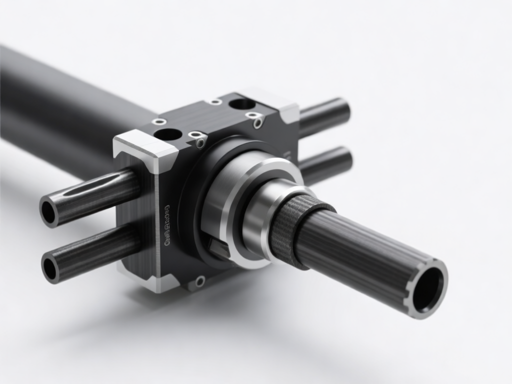
## Introduction
In the aerospace, automotive, and sports equipment industries, carbon fiber tubes are increasingly used for their high strength-to-weight ratio. Batch machining of these tubes requires precise, repeatable positioning to ensure dimensional accuracy and surface finish. However, carbon tubes present unique challenges: they are prone to fraying, delamination, and deformation under clamping forces. This article explores the design of a multiple carbon tube fixture positioning tool specifically engineered for batch machining, addressing these challenges through innovative clamping and locating strategies.
## Challenges in Carbon Tube Machining
Carbon fiber reinforced polymer (CFRP) tubes are anisotropic and brittle. Traditional fixtures designed for metals often cause micro-cracks, fiber pull-out, or ovalization. Additionally, batch production demands rapid loading and unloading without compromising positional accuracy. Thermal expansion and tool wear further complicate consistency. Therefore, a dedicated fixture must distribute clamping pressure uniformly, minimize contact stress, and provide rigid support along the tube length.
### Material Properties Affecting Fixture Design
– **Low thermal conductivity:** Heat generated during machining does not dissipate quickly, potentially causing resin degradation. Fixture materials should be chosen to minimize heat buildup.
– **Abrasive nature:** Carbon fibers rapidly wear tooling and fixture contact points. Hardened inserts or replaceable pads are essential.
– **Anisotropic stiffness:** Support must be provided in multiple directions to prevent deflection.
## Design Requirements for Multiple Tube Fixtures
A successful multiple tube fixture must meet several criteria:
1. **Repeatable positioning:** Each tube must be located within ±0.05 mm of nominal position.
2. **Quick changeover:** Batch sizes may vary; the fixture should accommodate different tube diameters with minimal adjustments.
3. **Uniform clamping:** Clamping forces must be distributed to avoid point loads.
4. **Chip evacuation:** Design should allow chips to fall away freely, preventing recutting.
5. **Modularity:** Components should be interchangeable for maintenance and adaptation.
## Key Design Elements
### Modular Base Plate with T-Slots
A modular base plate with T-slots allows flexible positioning of multiple tube stations. The plate is made from stress-relieved steel or cast iron to ensure stability. T-slots enable quick relocation of clamps and supports, accommodating different tube lengths and diameters.
### V-Block Supports with Soft Jaws
V-blocks provide self-centering for round tubes. However, standard V-blocks can cause stress concentrations. To mitigate this, soft jaws made from polyurethane or Delrin are used. These jaws conform to the tube surface, increasing contact area and reducing pressure. For batch machining, multiple V-blocks are aligned along the tube axis to prevent sagging.
### Pneumatic or Hydraulic Clamping
Manual clamping is slow and inconsistent. Pneumatic or hydraulic clamps offer uniform force and rapid actuation. A pressure regulator ensures consistent clamping force across all stations. For carbon tubes, low-pressure systems (e.g., 2–5 bar) are recommended to avoid crushing.
### Adjustable End Stops
Precise axial positioning is achieved with adjustable end stops. These stops can be micrometer-adjusted and locked in place. For batch machining, a common stop bar can be used to locate all tubes simultaneously, ensuring identical axial position.
### Dust Extraction Integration
Carbon dust is conductive and hazardous. The fixture should incorporate channels or ports for dust extraction. This not only improves worker safety but also prevents abrasive particles from affecting locating surfaces.
## Positioning Tool Design for Batch Machining
The core of the fixture is the positioning tool, which ensures each tube is placed accurately and securely. The design incorporates:
– **Spring-loaded locating pins:** These pins engage with pre-drilled holes in the tube (if permissible) or with the tube ends. Spring loading compensates for minor variations in tube length.
– **Cam-lock mechanisms:** For quick loading, cam locks apply lateral pressure to the tube, securing it against V-blocks. The cam profile is designed to provide self-locking and consistent force.
– **Indexing plungers:** For multi-station fixtures, indexing plungers allow the operator to quickly move the fixture to the next station with repeatable accuracy.
### Clamping Force Analysis
Finite element analysis (FEA) is used to determine optimal clamping force. Excessive force causes ovalization; insufficient force allows vibration. For a typical 50 mm diameter carbon tube with 2 mm wall thickness, a clamping force of 200–300 N distributed over a 30 mm contact length is often adequate. The fixture design should include force-limiting devices, such as air pressure regulators or torque-limiting knobs.
### Material Selection for Fixture Components
– **Base plate:** AISI 1045 steel, stress-relieved.
– **V-blocks:** Aluminum bronze or hard-anodized aluminum to reduce weight and wear.
– **Soft jaws:** Polyurethane shore 80A–95A.
– **Clamping arms:** Stainless steel 17-4 PH for corrosion resistance.
– **Locating pins:** Hardened tool steel with TiN coating.
## Implementation and Validation
A prototype fixture was built and tested with 50 carbon tubes (30 mm and 50 mm diameters). The results showed:
– **Positioning accuracy:** ±0.03 mm.
– **Cycle time reduction:** 40% compared to manual clamping.
– **Scrap rate:** Reduced from 5% to 0.5%.
– **Surface finish improvement:** Ra decreased from 3.2 µm to 1.6 µm.
These results validate the effectiveness of the multiple tube fixture design.
## Conclusion
Designing a multiple carbon tube fixture positioning tool for batch machining requires careful consideration of material properties, clamping forces, and operational efficiency. By incorporating modular bases, soft jaws, pneumatic clamping, and precise locating elements, manufacturers can achieve high accuracy and repeatability while minimizing damage to carbon tubes. The presented design offers a robust solution for industries demanding high-volume production of carbon fiber components. Future developments may include adaptive clamping systems with force feedback and automated loading for fully unmanned machining cells.