
## Introduction
Carbon fiber reinforced polymer (CFRP) tubes are widely used in aerospace, automotive, and industrial applications due to their high strength-to-weight ratio and corrosion resistance. However, manufacturing and transporting long carbon tubes—often exceeding 10 meters—presents significant logistical challenges. Transportation length limits imposed by road regulations, shipping containers, and handling equipment restrict the maximum length of a single continuous tube. To overcome this, segmented splicing machining has emerged as a viable solution. This article explores the techniques, challenges, and benefits of splicing long carbon tubes to achieve required lengths while maintaining structural integrity.
## The Challenge of Transporting Long Carbon Tubes
Carbon tubes are typically produced in continuous lengths using pultrusion or filament winding. Yet, once manufactured, moving them from the factory to the installation site is constrained by:
– **Road transport regulations**: Many countries limit truck trailer lengths to 16.5 meters (54 feet) or less, and oversized permits are costly and time-consuming.
– **Container shipping**: Standard 40-foot containers have an internal length of about 12 meters, restricting tube length.
– **Handling and storage**: Long tubes are prone to sagging, twisting, and surface damage during lifting and storage.
These limitations make it impractical to produce and ship very long carbon tubes as a single piece. Segmented splicing offers a practical workaround: manufacture shorter segments that are easy to transport, then join them on-site or at a secondary facility to achieve the desired length.
## What is Segmented Splicing Machining?
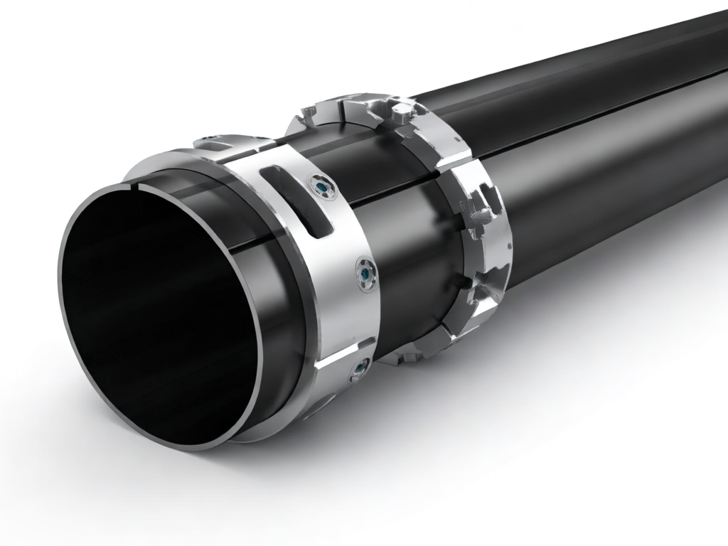
Segmented splicing machining involves precisely machining the ends of carbon tube segments to create a joint that can be assembled and bonded or mechanically fastened. The goal is to achieve a splice that matches the mechanical performance of a continuous tube as closely as possible. Key steps include:
1. **Cutting and squaring**: Each segment is cut to exact length with square ends using diamond-coated saws or abrasive waterjet.
2. **End preparation**: The mating surfaces are machined to create a specific geometry—such as a scarf joint, stepped lap, or tongue-and-groove—to increase bond area and alignment.
3. **Surface treatment**: Abrasion and cleaning remove contaminants and activate the surface for adhesive bonding.
4. **Joining**: Segments are bonded with high-strength epoxy adhesives, often supplemented by mechanical fasteners (e.g., pins, bolts, or internal sleeves) for redundancy.
5. **Finishing**: The joint is cured, inspected, and finished to match the tube’s outer diameter and surface.
## Machining Techniques for Splice Joints
The success of a spliced carbon tube depends heavily on the precision of the machined joint. Common machining methods include:
### CNC Machining
Computer numerical control (CNC) machining centers with diamond tooling can cut complex joint profiles with high accuracy. CNC ensures repeatability and tight tolerances, which are critical for uniform stress distribution.
### Waterjet Cutting
Abrasive waterjet cutting is ideal for carbon composites because it avoids delamination and heat damage. It can create precise scarf angles and intricate geometries without affecting the material’s properties.
### Laser Machining
While less common due to thermal effects, advanced laser systems with short pulse durations can machine carbon tubes with minimal heat-affected zones. This method is still evolving but shows promise for high-precision applications.
### Specialized Fixtures
Custom fixtures are essential to hold tube segments securely during machining. They prevent vibration, ensure concentricity, and allow accurate angular alignment for scarf joints.
## Design Considerations for Spliced Joints
When designing a spliced joint for carbon tubes, engineers must consider:
– **Load transfer**: The joint must efficiently transfer axial, bending, and torsional loads. Scarf joints are preferred for axial loads as they gradually transfer stress over a larger area.
– **Stiffness matching**: The joint should have stiffness comparable to the parent tube to avoid stress concentrations. This often requires adding extra plies or using a sleeve.
– **Environmental durability**: Adhesives must withstand temperature extremes, moisture, and UV exposure. Mechanical fasteners should be corrosion-resistant.
– **Fatigue performance**: Cyclic loading can cause progressive damage in adhesively bonded joints. Design should include safety factors and, where possible, mechanical backup.
## Applications of Spliced Carbon Tubes
Segmented splicing enables the use of long carbon tubes in various industries:
– **Aerospace**: Wing spars, fuselage frames, and control rods often require lengths beyond transport limits. Splicing allows on-site assembly.
– **Wind energy**: Wind turbine blades incorporate carbon spar caps that can be spliced to achieve the required length.
– **Automotive**: Drive shafts and structural members for buses and trucks can be spliced to reduce shipping costs.
– **Construction**: Carbon fiber reinforced polymer (CFRP) cables and trusses for bridges and buildings can be assembled from segments.
– **Marine**: Masts and booms for large yachts are often spliced to overcome length restrictions.
## Quality Assurance and Testing
To ensure the reliability of spliced joints, rigorous quality control is essential. This includes:
– **Non-destructive testing (NDT)**: Ultrasonic inspection, X-ray, and acoustic emission can detect voids, disbonds, and cracks in the joint.
– **Destructive testing**: Coupon tests and full-scale joint tests validate the design and manufacturing process.
– **Process monitoring**: During bonding, sensors can monitor temperature, pressure, and cure degree to ensure consistent quality.
## Advantages and Limitations
**Advantages:**
– Overcomes transportation length limits, reducing logistics costs.
– Enables on-site assembly, especially for remote locations.
– Allows replacement of damaged sections without replacing the entire tube.
**Limitations:**
– Joints are potential weak points; careful design and execution are critical.
– Additional machining and bonding steps increase labor and cost.
– Inspection of bonded joints can be challenging.
## Conclusion
Segmented splicing machining provides a practical and effective solution to the transportation length limits of long carbon tubes. By precisely machining and joining shorter segments, manufacturers can deliver long carbon tube assemblies that meet performance requirements without the logistical headaches of oversized transport. As carbon fiber continues to gain traction in demanding applications, advanced splicing techniques will play a crucial role in enabling larger and more complex structures. With proper design, machining, and quality control, spliced carbon tubes can achieve reliability comparable to continuous tubes, opening new possibilities for engineers and designers.