
## Introduction
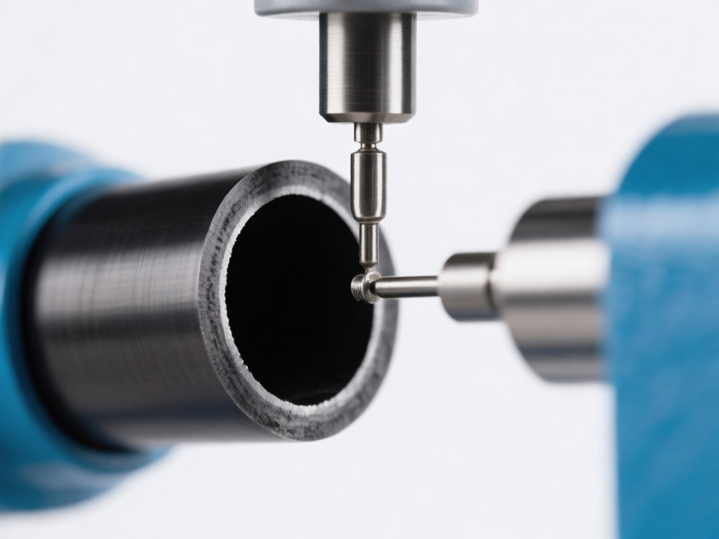
Miniature thin-wall carbon tubes are increasingly used in aerospace, medical devices, and high-performance sensors due to their exceptional strength-to-weight ratio and thermal stability. However, drilling micro tiny holes (typically <0.5 mm diameter) into these tubes presents unique challenges: the thin wall (often <0.2 mm) is prone to delamination, fiber pull-out, and thermal damage. This article explores the specialized drilling technologies, process parameters, and best practices for achieving precision micro holes in thin-wall carbon tubes without compromising structural integrity. ## Why Micro Hole Drilling in Thin-Wall Carbon Tubes Is Difficult Carbon fiber reinforced polymer (CFRP) and carbon nanotube (CNT) tubes are anisotropic and abrasive. When wall thickness is less than 0.2 mm, conventional drilling causes: - **Delamination**: Interlaminar cracks due to axial thrust force. - **Fiber pull-out**: Uncut fibers protruding from hole edges. - **Thermal degradation**: Resin burning from insufficient heat dissipation. - **Tool deflection**: Thin walls lack rigidity, leading to hole misalignment. These defects reduce fatigue life and sealing performance in applications like fuel injectors or microfluidic channels. ## Key Micro Drilling Technologies ### 1. Micro Electrical Discharge Machining (μEDM) μEDM uses spark erosion to remove material regardless of hardness. For carbon tubes, it minimizes mechanical stress. Key parameters: - Pulse duration: 0.5–5 μs - Discharge energy: 10–100 μJ - Electrode diameter: 0.05–0.3 mm (tungsten or brass) μEDM achieves holes down to 0.05 mm with no burrs, but requires conductive tubes. For non-conductive carbon composites, assistive electrodes or hybrid processes are needed. ### 2. Laser Drilling (UV and Femtosecond) UV nanosecond and femtosecond lasers offer non-contact drilling with minimal heat-affected zone (HAZ). - **UV laser (355 nm)**: Suitable for 0.1–0.5 mm holes, but carbon fiber absorbs strongly, causing taper. - **Femtosecond laser**: Ultra-short pulses (10⁻¹⁵ s) virtually eliminate HAZ and delamination. Hole diameters down to 20 μm. Laser drilling is ideal for thin walls but requires precise focal control and inert gas assist to prevent oxidation. ### 3. Micro Mechanical Drilling with Specialized Tools For cost-sensitive production, micro twist drills (0.1–0.5 mm) with diamond coating or PCD (polycrystalline diamond) are used. Success depends on: - **High spindle speed**: 20,000–100,000 rpm - **Low feed rate**: 0.5–5 μm/rev - **Peck drilling**: To clear chips and reduce thrust - **Backup support**: Sacrificial backing plate to prevent exit delamination ### 4. Ultrasonic-Assisted Drilling Vibrating the drill at 20–40 kHz reduces cutting force by 30–50%, minimizing delamination. This hybrid method is effective for thin-wall tubes where rigidity is low. ## Process Optimization for Thin-Wall Carbon Tubes ### Tool Geometry and Material - **Drill point angle**: 90°–118° for reduced thrust. - **Helix angle**: 30°–45° for efficient chip evacuation. - **Coating**: Diamond-like carbon (DLC) or CVD diamond to resist abrasion. ### Cutting Parameters | Parameter | Recommended Range | |-----------|-------------------| | Spindle speed | 30,000–80,000 rpm | | Feed rate | 1–10 μm/rev | | Peck depth | 0.05–0.2 mm | | Coolant | Air/oil mist or cryogenic CO₂ | ### Support and Fixturing - Use a **mandrel** inside the tube to support the wall. - Apply **sacrificial layer** (e.g., phenolic backing) on exit side. - **Zero-clearance clamping** to damp vibration. ## Quality Inspection and Defect Mitigation After drilling, inspect for: - **Hole diameter tolerance**: ±5 μm achievable with laser or μEDM. - **Delamination factor**: Should be <1.1 (ratio of max damage diameter to hole diameter). - **Surface roughness**: Ra <0.5 μm for sealing applications. Non-destructive methods: optical microscopy, X-ray CT, and acoustic emission monitoring during drilling. ## Applications and Case Studies - **Medical catheters**: Micro holes for drug delivery (0.1 mm in 0.15 mm wall). - **Aerospace fuel nozzles**: 0.2 mm holes in carbon composite tubes for cooling. - **Microfluidic devices**: Arrays of 50 μm holes in carbon nanotube membranes. A recent study achieved 0.08 mm holes in 0.1 mm wall carbon tubes using femtosecond laser with <5 μm HAZ, demonstrating feasibility for high-precision applications. ## Conclusion Micro tiny hole drilling in miniature thin-wall carbon tubes demands a tailored approach. While μEDM and femtosecond laser excel in precision, mechanical micro drilling with ultrasonic assistance offers a cost-effective alternative for larger volumes. Success hinges on controlling thrust force, thermal load, and wall support. As carbon tubes shrink in size and grow in application, hybrid and laser-based technologies will dominate, enabling next-generation lightweight, high-performance systems.