
## Introduction
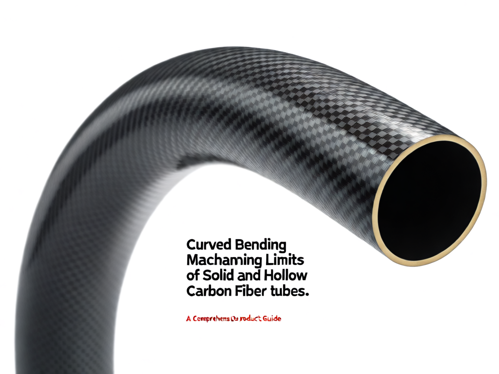
Carbon fiber reinforced polymer (CFRP) tubes are widely used in aerospace, automotive, sports equipment, and industrial machinery due to their exceptional strength-to-weight ratio and stiffness. However, when these tubes must be bent into curved shapes, manufacturers face significant challenges. The machining limits for curved bending of solid and hollow carbon fiber tubes are governed by material properties, tube geometry, and process parameters. This article explores the key factors that define these limits, providing engineers and manufacturers with essential insights to optimize design and production.
## Understanding Carbon Fiber Tube Bending
Bending carbon fiber tubes is not a simple plastic deformation process like metal bending. CFRP is a composite material with anisotropic properties, meaning its behavior differs based on fiber orientation. When subjected to bending forces, carbon fibers can fracture, delaminate, or buckle rather than yield. Therefore, the bending limits are determined by the maximum strain the material can withstand before failure.
### Solid vs. Hollow Tubes: Key Differences
Solid carbon fiber tubes consist of unidirectional or woven fibers throughout the cross-section, offering high stiffness but limited flexibility. Hollow tubes, typically produced by filament winding or roll-wrapping, have a central void that reduces weight but introduces buckling risks under bending. The bending limits for each type vary significantly due to differences in wall thickness, fiber architecture, and failure modes.
## Bending Limits of Solid Carbon Fiber Tubes
Solid carbon fiber tubes are generally stiffer and can withstand higher bending moments before failure compared to hollow tubes of the same outer diameter. However, their maximum bend radius is limited by the tensile strain on the outer surface and compressive strain on the inner surface. The critical limit is often the compressive strength, as carbon fibers are weaker in compression than tension.
### Factors Influencing Solid Tube Bending Limits
– **Fiber orientation**: Unidirectional fibers aligned with the tube axis provide high bending stiffness but low transverse strength. Angle-ply layups can improve bendability but reduce axial stiffness.
– **Resin system**: The matrix resin’s elongation at break affects the overall strain limit. Toughened epoxies allow slightly tighter bends.
– **Tube diameter and wall thickness**: Larger diameters and thicker walls increase stiffness but reduce the maximum curvature before failure.
– **Surface defects**: Machining marks or scratches can initiate cracks, lowering the bending limit.
### Typical Bend Radius Limits
For solid carbon fiber tubes with standard modulus fibers and epoxy resin, the minimum bend radius (measured to the tube centerline) is often 10 to 20 times the outer diameter (D). For example, a 10 mm solid tube may bend to a radius of 100–200 mm. High-strain fibers and optimized layups can push this limit to 5–10D, but at the cost of reduced stiffness.
## Bending Limits of Hollow Carbon Fiber Tubes
Hollow carbon fiber tubes are more prone to local buckling and ovalization during bending. The absence of core material means the tube wall must resist compressive stresses without support. As a result, the bending limits are generally lower than those of solid tubes of the same outer diameter, unless the wall thickness is increased.
### Factors Influencing Hollow Tube Bending Limits
– **Wall thickness**: Thicker walls improve resistance to buckling but increase weight and reduce flexibility. The diameter-to-thickness ratio (D/t) is a critical parameter; lower ratios allow tighter bends.
– **Fiber architecture**: Filament-wound tubes with optimized winding angles (e.g., ±45°) can distribute bending stresses more effectively than unidirectional tubes.
– **Internal support**: Using a mandrel or filling the tube with a removable core during bending can prevent collapse, allowing tighter radii.
– **Bending method**: Rotary draw bending, press bending, and roll bending each impose different stress states. Rotary draw bending with a mandrel is often preferred for tight radii.
### Typical Bend Radius Limits
For hollow carbon fiber tubes with a D/t ratio of 20 (e.g., 20 mm OD, 1 mm wall), the minimum bend radius is typically 15–25D. Thicker-walled tubes (D/t < 10) can achieve 8–15D. Advanced techniques like hot bending or internal pressure assistance can reduce these limits further, but may compromise surface finish or require post-processing. ## Machining Considerations for Curved Bending Achieving curved bends in carbon fiber tubes often requires machining operations such as trimming, drilling, or milling before or after bending. These processes introduce additional limits: - **Delamination risk**: Machining can cause interlayer separation, especially at edges. Diamond-coated tools and low feed rates minimize this. - **Fiber pull-out**: Improper cutting parameters can pull fibers, creating stress concentrations that lower bending limits. - **Heat generation**: Excessive heat during machining can degrade the resin matrix, reducing the tube's bending capacity. - **Springback**: After bending, carbon fiber tubes exhibit minimal springback compared to metals, but residual stresses can cause distortion during subsequent machining. ## Design and Process Optimization To maximize the bending limits of carbon fiber tubes, consider the following strategies: - **Optimize layup**: Use a combination of axial and off-axis plies to balance stiffness and bendability. - **Increase wall thickness locally**: In hollow tubes, thickening the bend region can prevent buckling. - **Use internal supports**: Mandrels or soluble cores can maintain cross-section integrity during bending. - **Control machining parameters**: Sharp tools, appropriate speeds and feeds, and coolant can reduce defects. - **Simulate before production**: Finite element analysis (FEA) can predict strain levels and identify failure points. ## Conclusion The curved bending machining limits of solid and hollow carbon fiber tubes are dictated by a complex interplay of material properties, tube geometry, and processing methods. Solid tubes offer higher bending stiffness but are limited by compressive failure, while hollow tubes are more susceptible to buckling and require careful design to achieve tight radii. By understanding these limits and employing optimized layups, tooling, and machining practices, manufacturers can successfully produce curved carbon fiber tubes for demanding applications. As carbon fiber technology advances, new materials and techniques will continue to push the boundaries of what is possible.