## Introduction
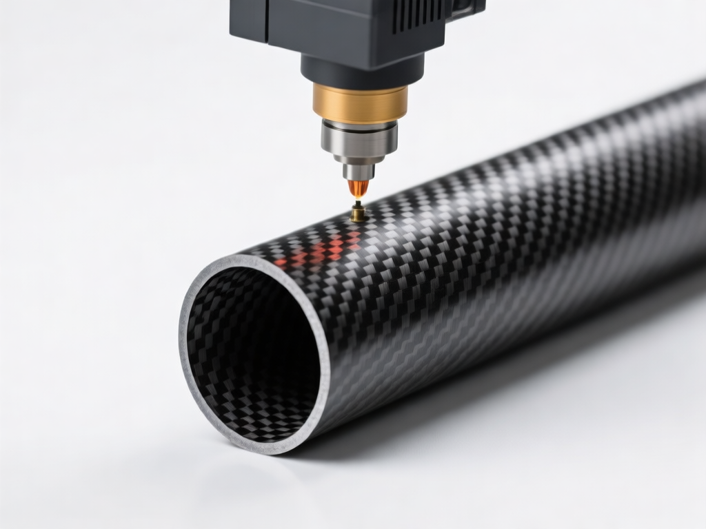
Carbon fiber reinforced polymer (CFRP) tubes are widely used in aerospace, automotive, sports equipment, and industrial machinery due to their exceptional strength-to-weight ratio. However, marking these tubes for identification, traceability, or branding presents a unique challenge: the laser marking process must not compromise the internal fiber structure. Unlike metals or plastics, carbon fiber tubes consist of brittle carbon fibers embedded in a polymer matrix. Any excessive heat input can cause matrix degradation, fiber breakage, or delamination, leading to catastrophic failure. This article explores the principles, challenges, and best practices for laser marking carbon tube surfaces without damaging the internal fiber structure.
## Understanding the Carbon Fiber Tube Structure
### Composition and Sensitivity
A typical carbon fiber tube is made of multiple layers of carbon fibers oriented in different directions, bonded together by an epoxy or other polymer resin. The fibers provide tensile strength, while the resin transfers load between fibers and protects them from environmental factors. The internal fiber structure is highly sensitive to thermal damage. When a laser beam hits the surface, it is absorbed by the carbon fibers and the resin, generating heat. If the heat is not carefully controlled, it can vaporize the resin, char the fibers, or create micro-cracks that propagate under load.
### Why Traditional Marking Methods Fail
Traditional marking methods such as inkjet, pad printing, or mechanical engraving are often unsuitable for carbon fiber tubes. Inks may not adhere well to the smooth, chemically inert surface, and mechanical engraving can sever fibers, creating stress concentrations. Laser marking, when properly controlled, offers a non-contact, permanent solution that can mark complex patterns without mechanical stress. However, the key is to avoid thermal damage to the underlying fibers.
## The Laser Marking Process: Principles and Parameters
### How Laser Marking Works on Carbon Fiber
Laser marking on carbon fiber typically uses a focused beam of infrared light (e.g., 1064 nm from a fiber laser or 10600 nm from a CO2 laser) to interact with the material. The goal is to alter the surface appearance—either by removing a thin layer of resin (ablation), causing controlled charring, or inducing a color change—without affecting the fibers below. The interaction depends on the laser wavelength, pulse duration, power density, and the optical properties of the carbon fiber composite.
### Critical Parameters for Damage-Free Marking
To mark without damaging internal fibers, several parameters must be optimized:
– **Wavelength**: Fiber lasers (1064 nm) are often preferred because carbon fibers absorb this wavelength well, allowing precise energy deposition near the surface. CO2 lasers (10600 nm) may be absorbed too superficially by the resin, leading to uneven marking.
– **Pulse Duration**: Ultra-short pulses (nanosecond, picosecond, or femtosecond) minimize the heat-affected zone (HAZ). Shorter pulses reduce thermal diffusion into the fibers.
– **Power Density**: Low to moderate power densities are essential. Excessive power can cause deep ablation and fiber damage.
– **Scan Speed and Overlap**: Higher scan speeds with minimal overlap reduce heat accumulation. Multiple passes at low power are often safer than a single high-power pass.
– **Focus Position**: Keeping the beam slightly defocused can distribute energy over a larger area, reducing peak intensity.
– **Assist Gas**: Using an inert gas (e.g., nitrogen or argon) can suppress oxidation and cooling, further protecting the fibers.
## Potential Damage Mechanisms and How to Avoid Them
### Thermal Damage to the Polymer Matrix
The polymer matrix (e.g., epoxy) has a relatively low decomposition temperature (typically 300–400°C). If the laser energy raises the local temperature above this threshold, the resin degrades, leading to loss of load transfer and potential delamination. To avoid this, the laser parameters must ensure that the heat-affected zone remains confined to the top few micrometers of the resin-rich surface layer. Using short pulses and low fluence (energy per unit area) prevents excessive heating.
### Fiber Breakage and Delamination
Carbon fibers themselves can withstand high temperatures (up to 1000°C in inert atmosphere), but they are brittle and can break if subjected to thermal shock or mechanical stress. Rapid heating and cooling can create thermal stresses that cause micro-cracks in the fibers or at the fiber-matrix interface. Delamination—separation between layers—can occur if the resin between layers is degraded. To prevent this, the marking depth must be strictly controlled to stay within the surface resin layer, never reaching the first fiber layer. Non-destructive evaluation (NDE) techniques such as microscopy or ultrasonic testing can verify that the internal structure remains intact.
### Charring and Color Change
Charring of the resin is often used for marking, as it creates a dark, permanent contrast. However, excessive charring can indicate that the fibers are also being affected. A controlled charring process uses low power and fast scanning to darken only the surface resin without burning into the fibers. Alternatively, some lasers can induce a color change in the resin without ablation, offering a safer marking method.
## Best Practices for Laser Marking Carbon Fiber Tubes
### Material-Specific Parameter Development
Every carbon fiber tube may have a different resin system, fiber volume fraction, and surface finish. Therefore, parameter development should be done on representative samples. A design of experiments (DOE) approach can identify the optimal settings that produce a clear mark while minimizing the heat-affected zone. Key responses to measure include mark contrast, mark depth, and evidence of fiber damage via cross-sectional microscopy.
### Use of Advanced Laser Technologies
– **Fiber Lasers with MOPA Technology**: MOPA (Master Oscillator Power Amplifier) fiber lasers allow independent adjustment of pulse duration and frequency, providing greater control over heat input. They are ideal for delicate marking on carbon fiber.
– **UV Lasers**: Ultraviolet lasers (355 nm) have shorter wavelengths and are absorbed more by the resin than by the fibers. This can lead to less fiber damage, as the energy is deposited in the resin, causing controlled ablation or color change.
– **Femtosecond Lasers**: These ultra-short pulse lasers ablate material with virtually no heat transfer, making them the safest for carbon fiber. However, they are more expensive and slower.
### Surface Preparation and Post-Processing
Cleaning the tube surface before marking removes contaminants that could absorb laser energy unevenly. After marking, a gentle cleaning with isopropyl alcohol can remove debris. In some cases, a protective coating can be applied over the mark to seal any exposed fibers, though this is often unnecessary if the marking is shallow.
### Quality Control and Verification
To ensure that the internal fiber structure is not damaged, implement a quality control protocol:
– **Visual Inspection**: Check for discoloration, charring, or surface cracks.
– **Microscopy**: Cross-section the marked area and examine under a microscope to measure the depth of the heat-affected zone and check for fiber breakage or delamination.
– **Mechanical Testing**: Perform tensile or flexural tests on marked and unmarked tubes to compare strength. A safe marking process should not reduce mechanical properties by more than 5%.
– **Non-Destructive Testing**: Use ultrasonic C-scan or X-ray computed tomography to detect internal defects.
## Case Study: Marking Aerospace Carbon Fiber Tubes
In aerospace applications, carbon fiber tubes are used in control rods, struts, and structural components. Marking must comply with strict traceability requirements (e.g., AS9100) without compromising airworthiness. A typical process might use a 20W MOPA fiber laser with a 1064 nm wavelength, pulse duration of 100 ns, frequency of 50 kHz, and a scan speed of 1000 mm/s. The mark is created by removing a thin layer of resin (about 10 µm deep) to expose the carbon fibers underneath, creating a contrasting dark mark. Cross-sectional analysis confirms that the fibers remain intact and the heat-affected zone is less than 20 µm. Mechanical testing shows no significant reduction in tensile strength.
## Conclusion
Laser marking on carbon fiber tubes is a viable and efficient method for permanent identification, provided that the process is carefully controlled to avoid damage to the internal fiber structure. By understanding the material properties, optimizing laser parameters, and implementing rigorous quality control, manufacturers can achieve high-contrast, durable marks without compromising the structural integrity of the tube. As laser technology advances, especially with ultra-short pulse and UV lasers, the window for safe marking will continue to expand, enabling broader adoption in critical industries.