
## Introduction
In modern industrial design and structural engineering, square carbon tubes have become a cornerstone material for lightweight, high-strength frameworks. Their application in multi-angle bracket assembly structures—such as robotic arms, aerospace jigs, automotive roll cages, and modular framing systems—demands meticulous attention to wall thickness selection. The wall thickness not only dictates the tube’s load-bearing capacity and stiffness but also influences the integrity of the joints where brackets are attached. This article provides a comprehensive guide to selecting the optimal wall thickness for square carbon tubes in multi-angle bracket assemblies, balancing mechanical performance, manufacturability, and cost.
## Understanding Square Carbon Tubes
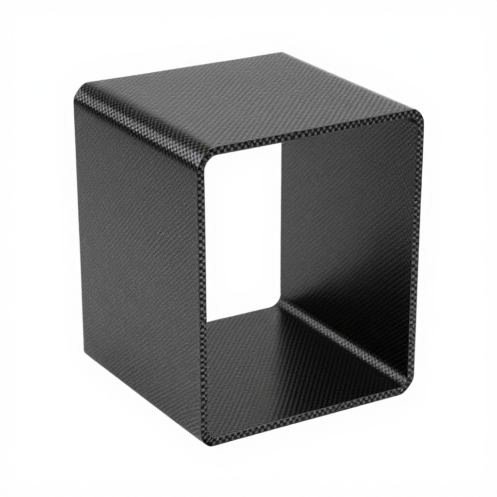
Square carbon tubes are manufactured from carbon fiber reinforced polymer (CFRP), offering exceptional strength-to-weight ratios compared to metals like steel or aluminum. The square cross-section provides inherent torsional rigidity and simplifies bracket mounting due to flat surfaces. The wall thickness—typically ranging from 1 mm to 10 mm—is a critical parameter that defines the tube’s structural behavior.
### Key Mechanical Properties
– **Tensile Strength**: Carbon fiber composites exhibit high tensile strength, often exceeding 600 MPa.
– **Modulus of Elasticity**: Stiffness ranges from 70 to 150 GPa depending on fiber orientation.
– **Density**: Approximately 1.6 g/cm³, significantly lighter than steel (7.8 g/cm³).
These properties make square carbon tubes ideal for applications where weight reduction is paramount without compromising structural integrity.
## The Role of Wall Thickness in Bracket Assemblies
In multi-angle bracket assemblies, the tube serves as the primary load-bearing member, while brackets—typically made of aluminum or steel—are bolted or bonded to the tube’s surface. The wall thickness directly affects:
– **Localized Stress Distribution**: Thinner walls are more susceptible to stress concentrations at bracket attachment points, leading to premature failure.
– **Bending and Torsional Stiffness**: Thicker walls increase the moment of inertia, enhancing resistance to bending and twisting.
– **Joint Integrity**: Adequate wall thickness ensures sufficient material for threaded inserts, rivets, or adhesive bonding, preventing pull-out or delamination.
## Factors Influencing Wall Thickness Selection
### 1. Load Requirements
The magnitude and direction of applied loads are paramount. For static loads, a simplified stress analysis can determine the minimum wall thickness. For dynamic loads (e.g., vibration, impact), a higher safety factor is necessary, requiring thicker walls.
### 2. Bracket Configuration and Angle
Multi-angle brackets introduce complex load paths. At acute angles, the bracket exerts concentrated forces on the tube wall. Thicker walls distribute these forces over a larger area, reducing peak stress.
### 3. Tube Dimensions
Larger cross-sectional dimensions (e.g., 50 mm x 50 mm) can accommodate thinner walls compared to smaller tubes (e.g., 20 mm x 20 mm) for the same load, due to increased geometric stiffness.
### 4. Manufacturing Constraints
Carbon tube production methods, such as pultrusion or roll wrapping, have minimum and maximum wall thickness limits. Additionally, drilling holes for brackets can weaken the tube; thicker walls provide more residual strength after machining.
### 5. Environmental Conditions
Temperature extremes, moisture, and chemical exposure can degrade the resin matrix. A thicker wall offers better protection against environmental penetration and delamination.
## Selecting the Optimal Wall Thickness: A Step-by-Step Approach
### Step 1: Define Load Cases
Identify all potential load scenarios, including static, dynamic, and impact loads. Calculate the maximum bending moment, shear force, and torque acting on the tube.
### Step 2: Perform Stress Analysis
Using finite element analysis (FEA) or analytical formulas, determine the stress distribution in the tube wall. Compare the computed stress with the allowable stress of the carbon composite (typically 30-50% of ultimate tensile strength for safety).
### Step 3: Evaluate Joint Stiffness
For bracket assemblies, the stiffness of the connection is crucial. Thicker walls reduce deflection at the joint, maintaining alignment and preventing loosening of fasteners.
### Step 4: Consider Weight and Cost Trade-offs
Thicker walls increase weight and material cost. Optimize by selecting the thinnest wall that meets all structural requirements, but avoid marginal designs that may fail under unforeseen conditions.
### Step 5: Prototype and Test
Always validate the selected wall thickness through physical testing. Prototype assemblies should undergo load testing to confirm FEA predictions and ensure reliability.
## Common Wall Thickness Ranges and Applications
| Wall Thickness | Typical Applications |
|—————-|———————-|
| 1.5 – 2.0 mm | Light-duty frames, non-structural brackets, prototypes |
| 2.5 – 3.0 mm | General-purpose assemblies, medium loads, robotic arms |
| 3.5 – 5.0 mm | Heavy-duty structures, aerospace jigs, automotive roll cages |
| > 5.0 mm | Extreme load applications, high-impact environments |
## Impact of Wall Thickness on Bracket Attachment Methods
### Bolted Connections
For bolted brackets, the wall thickness must accommodate threads or inserts. A minimum of 2 mm is often required for reliable thread engagement. Thicker walls allow for deeper inserts, increasing pull-out strength.
### Adhesive Bonding
When bonding brackets, the bond area and peel strength are critical. Thicker walls provide a larger bonding surface and reduce peel stresses at the edges.
### Riveted Joints
Riveting requires sufficient wall thickness to prevent deformation during installation. A wall thickness of at least 2.5 mm is recommended for standard rivets.
## Case Study: Multi-Angle Bracket Assembly for a Robotic Arm
Consider a robotic arm with a square carbon tube of 40 mm x 40 mm, supporting a payload of 50 kg at a distance of 1 meter. The bracket is attached at a 45-degree angle, creating a combined bending and torsional load. FEA analysis reveals a maximum stress of 120 MPa at the bracket edge. Using a safety factor of 2, the allowable stress is 150 MPa (assuming ultimate strength of 300 MPa). A wall thickness of 3 mm provides a moment of inertia that keeps stress below the limit, while also offering adequate material for threaded inserts. The final selection is 3 mm, balancing weight and performance.
## Common Pitfalls in Wall Thickness Selection
– **Over-thinning**: Choosing too thin a wall to save weight can lead to catastrophic failure at bracket joints.
– **Ignoring Stress Concentrations**: Sharp corners in brackets or abrupt changes in tube cross-section can amplify stress.
– **Neglecting Environmental Factors**: UV exposure and moisture can weaken thin walls over time.
– **Inadequate Testing**: Relying solely on calculations without prototype testing can miss manufacturing defects.
## Conclusion
Selecting the appropriate wall thickness for square carbon tubes in multi-angle bracket assembly structures is a critical engineering decision. It requires a holistic approach that considers load requirements, bracket geometry, manufacturing constraints, and environmental conditions. By following a systematic analysis and validation process, engineers can achieve a design that is both lightweight and robust, ensuring long-term reliability and performance. Remember, the optimal wall thickness is not always the thickest or thinnest—it is the one that meets all functional requirements with minimal material usage.