
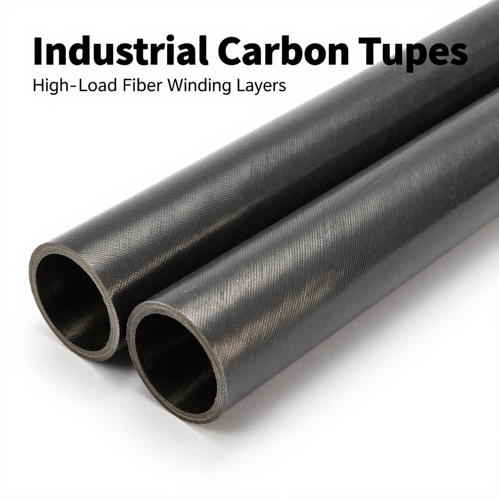
# How to Confirm Fiber Winding Layers When Ordering High-Load Industrial Carbon Tubes
## Introduction
When sourcing high-load industrial carbon tubes, the fiber winding layer configuration is one of the most critical specifications that determines mechanical performance, durability, and cost. Unlike standard tubes, high-load applications—such as aerospace actuators, robotic arms, hydraulic cylinders, and structural supports—require precise control over fiber orientation, layer count, and winding pattern. Miscommunication or guesswork in this area can lead to premature failure, safety hazards, and costly rework. This article provides a systematic approach to confirming fiber winding layers with your manufacturer, ensuring your carbon tubes meet exact load-bearing requirements.
## Understanding Fiber Winding Layers
### What Are Winding Layers?
Fiber winding layers refer to the number of individual plies of carbon fiber (or other reinforcing fibers) that are wound around a mandrel at specific angles to form the tube wall. Each layer contributes to the tube’s strength, stiffness, and resistance to internal pressure, torsion, and bending. The layers are typically applied in a sequence, with each ply having a defined orientation (e.g., ±45°, 0°, 90°) relative to the tube axis.
### Why Layer Count Matters
In high-load applications, the layer count directly influences the tube’s load-carrying capacity. More layers generally increase wall thickness and structural integrity, but they also add weight and cost. Conversely, insufficient layers can lead to delamination, cracking, or catastrophic failure under stress. Therefore, confirming the exact number of layers is not just a technical detail—it is a safety and performance imperative.
## Key Factors Influencing Winding Layer Requirements
### Load Type and Magnitude
The first step is to define the load conditions: axial tension/compression, bending, torsion, or internal pressure. Each load type stresses the tube differently, and the winding layer design must be optimized accordingly. For example, axial loads require more 0° (longitudinal) layers, while torsional loads demand ±45° layers. The magnitude of the load (in Newtons or pounds) will dictate the total wall thickness and, consequently, the number of layers.
### Tube Dimensions and Geometry
Outer diameter, inner diameter, and length all affect layer calculations. A larger diameter tube with the same wall thickness will have a higher moment of inertia, but the stress distribution changes. Manufacturers use finite element analysis (FEA) to determine the optimal layer count based on your specific geometry and load envelope.
### Material Properties
Carbon fiber comes in various grades (e.g., T300, T700, T800) with different tensile strengths and moduli. The fiber areal weight (g/m²) and resin system also influence how many layers are needed to achieve a target strength. Higher-grade fibers may allow fewer layers, but they are more expensive. Confirm with your supplier which fiber type is being used and how it affects layer count.
### Safety Factor and Design Standards
Industrial applications often require a safety factor of 2 to 3 times the maximum expected load. This factor must be incorporated into the layer count. Additionally, industry standards (e.g., ISO, ASTM) may mandate minimum layer counts or specific winding patterns for certain applications. Always verify compliance with relevant standards.
## Step-by-Step Process to Confirm Winding Layers
### Step 1: Define Your Load Requirements Clearly
Provide your manufacturer with a detailed load specification sheet, including:
– Maximum axial load (tension and compression)
– Maximum bending moment
– Maximum torque
– Internal pressure (if applicable)
– Operating temperature range
– Expected fatigue life (number of cycles)
This data allows the manufacturer to run structural simulations and propose a layer schedule.
### Step 2: Request a Detailed Layer Schedule
Ask the manufacturer for a formal layer schedule document that lists:
– Total number of layers
– Orientation of each layer (e.g., [0/±45/90]s)
– Fiber type and areal weight per layer
– Resin system and cure cycle
– Resulting wall thickness and fiber volume fraction
This schedule is your primary confirmation tool. Do not accept vague statements like “standard layup”—demand specifics.
### Step 3: Validate with Mechanical Testing
Before mass production, request test coupons or prototype tubes that match the proposed layer schedule. Conduct mechanical tests (tensile, compression, torsion, burst) to verify that the actual performance meets your load requirements. Compare test results with theoretical calculations. If discrepancies arise, revisit the layer count or orientation.
### Step 4: Review Quality Control Documentation
Ensure the manufacturer provides quality control (QC) documentation for each production batch, including:
– Ultrasonic inspection results (to detect voids or delamination)
– Layer count verification (e.g., via microscopy on cross-sections)
– Dimensional checks (wall thickness, diameter)
– Fiber volume fraction analysis
These records confirm that the delivered tubes match the confirmed layer schedule.
### Step 5: Establish a Change Management Protocol
If you need to alter load conditions or dimensions in the future, have a formal process to re-evaluate the winding layer design. Any change in load, material, or geometry should trigger a new layer confirmation cycle, not just a verbal adjustment.
## Common Pitfalls and How to Avoid Them
### Assuming More Layers Always Means Stronger
While more layers generally increase strength, they also increase weight and cost. Over-engineering can lead to unnecessary expense and reduced performance in dynamic applications. Use engineering analysis to find the optimal layer count, not just the maximum.
### Ignoring Winding Pattern
Layer count alone is insufficient—the winding pattern (e.g., hoop, helical, polar) and sequence matter. Two tubes with the same number of layers but different orientations can have vastly different load capacities. Always specify the full layup sequence.
### Overlooking Resin Content
High resin content can weaken the tube despite a high layer count. Confirm that the fiber volume fraction is within the recommended range (typically 55-65%) for structural applications.
### Not Considering End Effects
In high-load applications, the tube ends often experience stress concentrations. The layer schedule may need additional reinforcement at the ends (e.g., extra hoop layers). Discuss this with your manufacturer.
## Communicating with Your Manufacturer
### Use a Technical Drawing or Specification Sheet
Create a clear specification sheet that includes a diagram of the tube with dimensions and a table of load requirements. This minimizes misinterpretation.
### Ask for Simulation Reports
Reputable manufacturers will provide FEA reports showing stress distribution and predicted failure modes. Review these reports to ensure the layer count is justified.
### Request a Written Warranty
A warranty that explicitly states the tube’s load rating based on the confirmed layer schedule protects you in case of premature failure.
## Conclusion
Confirming fiber winding layers when ordering high-load industrial carbon tubes is a multi-step process that requires clear communication, technical documentation, and validation. By defining your load requirements, requesting a detailed layer schedule, testing prototypes, and reviewing QC records, you can ensure that the tubes you receive are precisely engineered for your application. Remember that layer count is not a standalone number—it is part of a complex design that includes fiber orientation, material properties, and manufacturing quality. Take the time to verify every detail, and your carbon tubes will deliver reliable, high-performance service under the most demanding conditions.