
## Introduction
High-speed equipment, ranging from CNC spindles and robotic arms to aerospace actuators and precision printing rollers, demands structural components that exhibit exceptional stiffness-to-weight ratios and dimensional stability. Carbon fiber reinforced polymer (CFRP) tubes, particularly those manufactured via multi-layer winding, have emerged as a preferred solution. However, at elevated rotational speeds and dynamic loads, vibration becomes a critical limiting factor. Excessive vibration leads to accelerated wear, reduced machining accuracy, and catastrophic resonance failures. Therefore, rigorous vibration attenuation testing of multi-layer winding carbon tubes is essential to validate their performance and ensure operational reliability.
This article provides a comprehensive technical overview of vibration attenuation testing for multi-layer winding carbon tubes used in high-speed equipment. It details the test objectives, methodologies, instrumentation, data analysis, and interpretation of results, with a focus on damping ratio, natural frequency, and transmissibility.
## Why Vibration Attenuation Matters in High-Speed Applications
In high-speed rotating systems, the tube acts as a structural shaft or beam. Vibration sources include unbalance, misalignment, bearing defects, and external excitations. If the excitation frequency approaches the tube’s natural frequency, resonance occurs, amplifying amplitudes by factors of 10 to 100. This can cause:
– **Loss of precision** – in machining or measurement systems.
– **Fatigue failure** – at the fiber-matrix interface or at end fittings.
– **Noise and heat generation** – reducing overall efficiency.
– **Reduced service life** – of bearings and adjacent components.
Multi-layer winding carbon tubes offer inherent damping due to the viscoelastic nature of the epoxy matrix and the frictional sliding between fiber layers. However, the degree of attenuation depends on winding angle, layer count, fiber type, and resin system. Testing quantifies these effects, allowing engineers to optimize layup schedules for specific operating speeds.
## Test Objectives
The primary objectives of vibration attenuation testing are:
1. **Determine natural frequencies** – to avoid resonance in the operating speed range.
2. **Measure damping ratio (ζ)** – indicating how quickly vibrations decay after excitation.
3. **Evaluate transmissibility** – the ratio of output to input vibration amplitude across the tube.
4. **Assess frequency response function (FRF)** – providing a complete dynamic signature.
5. **Compare different winding configurations** – to select the best design for a given application.
## Test Specimen Preparation
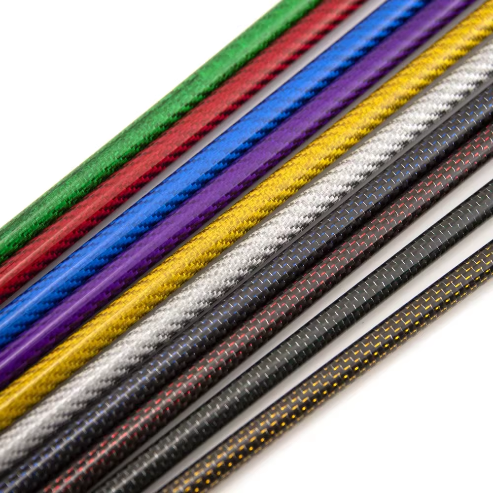
Multi-layer winding carbon tubes are manufactured by filament winding, where continuous carbon fiber tows are impregnated with resin and wound onto a mandrel at controlled angles. Typical layups include [±θ] angles such as ±15°, ±30°, ±45°, and ±60°, with multiple layers to achieve desired thickness. For testing, specimens are cut to a standardized length (e.g., 500 mm) with ends machined flat and parallel. The inner diameter, outer diameter, and wall thickness are measured precisely. Any surface defects or delaminations are inspected via ultrasonic C-scan prior to testing to ensure specimen integrity.
## Test Setup and Instrumentation
### 1. Excitation Methods
– **Impact Hammer Testing (Modal Analysis):** A calibrated impact hammer with a load cell strikes the tube at a defined point, imparting a broadband impulse. This excites multiple modes simultaneously. It is quick and suitable for initial characterization.
– **Electrodynamic Shaker Testing:** A shaker applies a controlled sinusoidal or random excitation over a frequency range (e.g., 10–2000 Hz). This allows steady-state response measurement and transmissibility evaluation.
– **Rotating Unbalance Excitation:** For high-speed equipment, the tube is mounted on a spindle and rotated at increasing speeds while measuring vibration at the bearing housings. This simulates real operating conditions.
### 2. Boundary Conditions
The tube is supported in a manner that mimics its actual installation. Common configurations include:
– **Free-free:** Suspended by soft elastic cords to simulate a free boundary, ideal for intrinsic material damping measurement.
– **Simply supported:** Placed on knife-edge supports at two points, representing a beam in bending.
– **Fixed-fixed:** Clamped at both ends, simulating a rigidly mounted shaft.
### 3. Sensors
– **Accelerometers:** Lightweight piezoelectric accelerometers (mass < 2 g) are attached at multiple points along the tube using wax or adhesive. They measure acceleration response. – **Strain Gauges:** For localized strain measurement, especially in high-frequency modes. – **Laser Doppler Vibrometer (LDV):** Non-contact measurement for high-speed rotation or high-temperature environments, avoiding mass loading effects. ### 4. Data Acquisition System A multi-channel data acquisition system with a high sampling rate (at least 10 times the highest frequency of interest) and anti-aliasing filters is used. The system records both input force and output acceleration signals simultaneously. ## Test Procedure ### Step 1: Modal Test (Impact Hammer) 1. Mount the tube in the chosen boundary condition. 2. Mark a grid of points (e.g., 10 points along the length) for measurement. 3. Strike each point with the hammer while measuring response at a fixed reference accelerometer (roving hammer, fixed response) or vice versa. 4. Record time-domain signals and compute the Frequency Response Function (FRF) for each point. 5. Average multiple impacts (typically 5–10) to reduce noise. ### Step 2: Damping Measurement 1. Excite the tube at its first natural frequency using a shaker or hammer. 2. Stop excitation abruptly and record the free decay of vibration. 3. Use the logarithmic decrement method to calculate the damping ratio: ζ = (1/(2πn)) * ln(A0/An) where A0 is the initial amplitude and An is the amplitude after n cycles. Alternatively, apply the half-power bandwidth method to the FRF peak: ζ = Δf / (2fn), where Δf is the bandwidth at 3 dB down from the peak. ### Step 3: Transmissibility Test 1. Mount the tube on a shaker with a rigid base. 2. Attach an accelerometer to the base (input) and another to the tube at a critical location (output). 3. Sweep frequency from low to high (e.g., 10–2000 Hz) at a constant acceleration amplitude. 4. Record the transmissibility ratio (output/input) as a function of frequency. ### Step 4: Rotating Test (if applicable) 1. Install the tube in a high-speed spindle with appropriate bearings. 2. Gradually increase rotational speed from zero to the maximum operating speed. 3. Measure vibration displacement or acceleration at the bearing caps using eddy current probes or accelerometers. 4. Identify any resonance peaks and record the amplitude at each speed. ## Data Analysis and Interpretation ### Frequency Response Function (FRF) The FRF magnitude shows peaks at natural frequencies. The first few bending modes are typically of interest. For a tube, the first natural frequency (fn) in bending can be approximated by: fn = (k² / (2πL²)) * sqrt(EI / (ρA)) where k is a constant depending on boundary conditions, L is length, E is modulus, I is area moment of inertia, ρ is density, and A is cross-sectional area. Multi-layer winding affects E and damping, thus shifting fn. ### Damping Ratio A higher damping ratio indicates better vibration attenuation. Typical CFRP tubes exhibit damping ratios from 0.5% to 2% for low-frequency modes, which is significantly higher than steel (0.1–0.3%). Multi-layer winding with interlayer friction can increase damping further, but may reduce stiffness. The test results guide the trade-off. ### Transmissibility At resonance, transmissibility can be very high. A well-damped tube will show a lower peak transmissibility (e.g., < 10) compared to a poorly damped one (e.g., > 30). Off-resonance, transmissibility should be near 1 (no amplification).
### Mode Shapes
By analyzing the phase and amplitude of FRFs across measurement points, mode shapes can be extracted. This helps identify whether the vibration is bending, torsion, or axial, and informs design modifications.
## Factors Affecting Vibration Attenuation
– **Winding Angle:** Lower angles (e.g., ±15°) provide higher axial stiffness but lower damping. Higher angles (e.g., ±45°) increase damping due to shear deformation between layers.
– **Layer Count:** More layers increase interlayer friction, enhancing damping, but also increase mass and cost.
– **Resin System:** Toughened epoxy resins exhibit higher viscoelastic damping than standard epoxies.
– **Fiber Type:** High-modulus fibers (e.g., M55J) are stiffer but less damped than standard modulus fibers (e.g., T700).
– **Preload and Boundary Conditions:** Clamping force and support stiffness affect the measured damping due to energy dissipation at interfaces.
## Case Study Example
Consider a multi-layer winding carbon tube with a layup of [±30°/±60°]4, outer diameter 50 mm, wall thickness 5 mm, and length 600 mm. Impact testing under free-free conditions revealed:
– First bending mode at 320 Hz with a damping ratio of 1.8%.
– Second bending mode at 780 Hz with a damping ratio of 1.5%.
– Transmissibility at first mode was 8.5.
In a rotating test up to 10,000 rpm (166.7 Hz), no resonance was encountered, and vibration amplitude at the bearing remained below 2 µm, well within acceptable limits. This validated the tube for use in a high-speed spindle application.
## Standards and Best Practices
Testing should follow established standards where applicable:
– **ASTM E756** – Standard Test Method for Measuring Vibration-Damping Properties of Materials.
– **ISO 7626** – Mechanical vibration and shock – Experimental determination of mechanical mobility.
– **ISO 10816** – Mechanical vibration – Evaluation of machine vibration by measurements on non-rotating parts.
Best practices include:
– Calibrate all sensors before each test.
– Use a consistent impact location and force level.
– Perform repeatability checks with at least three specimens per configuration.
– Document environmental conditions (temperature, humidity) as they affect resin damping.
– Use modal analysis software for curve fitting and parameter extraction.
## Conclusion
Vibration attenuation testing is indispensable for the design and qualification of multi-layer winding carbon tubes intended for high-speed equipment. Through modal analysis, damping measurement, and transmissibility evaluation, engineers can optimize the tube’s layup to achieve a balance between stiffness and damping, ensuring stable operation above critical speeds. The test results provide quantitative data that directly influences material selection, manufacturing process control, and final product performance. As rotational speeds continue to rise, robust vibration testing will remain a cornerstone of reliability engineering in advanced machinery.
By implementing the methodologies described in this article, manufacturers can deliver carbon tubes that not only meet but exceed the dynamic performance requirements of modern high-speed equipment.