
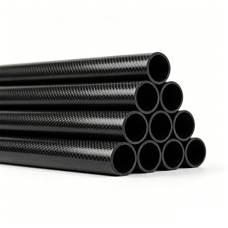
Introduction
Carbon fiber tubes have become a cornerstone material in industries ranging from aerospace to robotics, prized for their exceptional strength-to-weight ratio. However, the term "strength" is an oversimplification. In engineering practice, the suitability of a carbon fiber tube for a specific application is determined by its response to distinct loading conditions. This article provides a detailed breakdown of the three primary mechanical properties—tensile, bending, and shear strength—alongside the standardized testing methodologies used to quantify them. Understanding these parameters is critical for design engineers who must predict failure modes and ensure structural integrity.
Tensile Strength: Resistance to Axial Pull
Tensile strength measures a material's ability to withstand pulling forces along its longitudinal axis without fracturing. For carbon fiber tubes, this property is dominated by the orientation of the carbon fibers—unidirectional (0°) fibers yield the highest tensile performance, while woven or multi-axial layups exhibit lower values due to off-axis fiber misalignment.
Testing Methodology: The standard test is ASTM D3039, which uses flat coupons or full tube sections. The specimen is mounted in hydraulic grips and loaded at a constant crosshead speed (typically 2 mm/min) until failure. Strain is recorded via extensometers or digital image correlation (DIC).
Typical Values: High-modulus carbon fiber tubes can achieve tensile strengths of 2,000–3,500 MPa, with a modulus of elasticity between 230–400 GPa. Failure is often catastrophic and brittle, characterized by a sudden fracture with frayed fiber ends. Notably, the tensile strength is highly sensitive to void content, fiber volume fraction, and alignment; a 1% increase in void content can reduce tensile strength by up to 7%.
Bending Strength: Resistance to Flexural Loads
Bending (flexural) strength evaluates a tube's resistance to deformation and failure under a transverse load. This property is critical for components like drone arms, bicycle frames, and structural supports. In bending, the outer fibers experience maximum tensile stress while the inner fibers undergo compressive stress. As a result, failure often initiates on the tension side due to fiber rupture, or on the compression side due to micro-buckling of the fibers.
Testing Methodology: The three-point and four-point bending tests are the most common. In a three-point test (ASTM D7264), a single loading nose applies force at the midpoint of the tube, supported at two points. Four-point bending (ASTM D6272) uses two loading noses, creating a constant moment region, which better simulates real-world distributed loads. For tubes, the span-to-diameter ratio should exceed 16:1 to avoid shear-dominated failure.
Calculations and Behavior: Flexural stress is calculated using the beam theory equation: σ = (8FL) / (π(D₀⁴ – Dᵢ⁴)) × D₀, where F is the load, L is the support span, and D₀/Dᵢ are the outer and inner diameters. Typical flexural strengths range from 1,200–2,000 MPa. Unlike tensile failure, bending failure may be progressive; initial cracking is followed by delamination and a gradual load drop before complete fracture.
Shear Strength: Resistance to In-Plane and Interlaminar Forces
Shear strength is the most complex and often underestimated property of carbon fiber tubes. There are two primary shear modes: in-plane shear (resistance to forces parallel to the fiber direction) and interlaminar shear (resistance to sliding between adjacent layers). Interlaminar shear is particularly critical for tubes, as they are laminated structures; failure here occurs when the resin matrix that bonds the layers fails, not the fibers themselves.
Testing Methodology: The most common test for tubes is the short-beam shear test (ASTM D2344), also known as the three-point bend test with a very short span-to-thickness ratio (typically 4:1). This forces the specimen to fail in shear rather than in bending. For in-plane shear, the ±45° tensile test (ASTM D3518) is used, though it requires converting a tube into a flat laminate for coupon preparation.
Performance Characteristics: Interlaminar shear strength (ILSS) for carbon fiber tubes typically falls within 60–110 MPa. Failure appears as a horizontal crack along the neutral axis, often visible as a whitish delamination line. Because the resin is substantially weaker than the fiber, shear properties are highly temperature-dependent and degrade rapidly above the glass transition temperature (Tg) of the epoxy matrix.
Conclusion: Selecting a Tube Based on Loading Profile
No single mechanical property defines a tube's performance. An aerospace spar may demand high tensile strength, while a robotic arm needs robust bending stiffness, and a torque tube requires superior shear resistance. The manufacturer's data sheet should always report values from standard tests, but engineers must also consider the loading rate, environmental conditions, and notch sensitivity. A comprehensive design approach—testing actual tube samples under simulated service loads—remains the gold standard, as it captures the synergistic effects of these three distinct mechanical responses.